
|
Note—This procedure applies to the Transition, High Temp, and Amplification Incubators. |
Parts and Materials Required
- Hex key, 2.5 mm
- INCUBATOR (ALL), MAIN PCB
Time Required
- 10 minutes
Removal Procedure
|
|
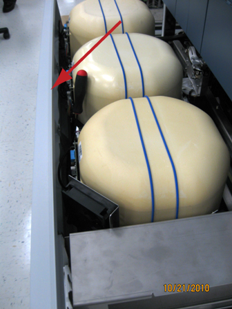
MTUs may be present in module. It is necessary to remove all MTUs to avoid contamination. |
- Put on proper PPE.
- Carefully open the Service Drawer.
- Remove the Mid Bay front panel.
 Using a long handled 4 mm Allen wrench, loosen the four 5 mm screws that secure the Mid Bay front panel.
- If removing an Amp Incubator PCB, the external fan does not need to be removed.
- Locate the Incubator that requires the PCB replacement.
- Remove the sheet metal cover holding the incubator cap in place. Some incubator versions have this in place and will cover the Incubator Main PCB.
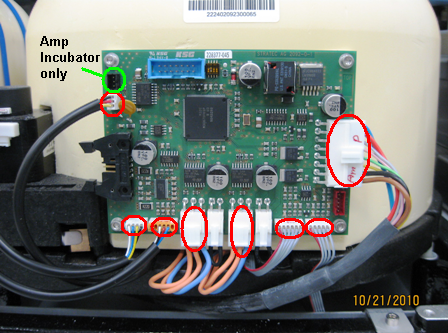
- Unplug the connectors that are plugged into the PCB (eight connections on the High Temperature and Transition Incubators, nine on the Amplification Incubator, ten on the Amplification Incubator with RTFs installed). There are two jumpers next to the heater foil connections that will need to be transferred to the new PCB.
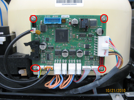
- Using a 2.5 mm hex key, remove the four 2.5 mm screws that secure the main PCB and remove the PCB from the incubator.
Replacement Procedure
- Verify that the DIP switch settings are correct according to the replaced Incubator's PCB.
DIP Switch Transition Incubator HT Incubator Amplification Incubator 1 ON OFF OFF 2 OFF OFF ON 3 OFF OFF OFF 4 OFF OFF OFF - Place the main PCB into the Incubator.
- Tighten the four 2.5 mm screws that secure the main PCB.
- Plug the connections into the main PCB.
Note—The label on the PCB is incorrectly reversed. Therefore, the Heat Housing (PCB) should be correctly connected to the bottom heater cable. The Heat Bottom (PCB) should be correctly connected to the side heater cable. - Install the incubator cap retaining band or sheet metal cover with retaining bands.
- Install the Mid Bay front panel.
- Close the Service Drawer.
- Run Instrument Setup (Firmware).
- Start up Service Software.
Alignment/Calibration
- Perform the incubator slot alignment procedure.
- Reteach the Linear Distributor to the incubator.
- Cloes the service drawer and reinstall the Luminometer injector.
 button at the top of the page to send feedback, comments, or change requests.
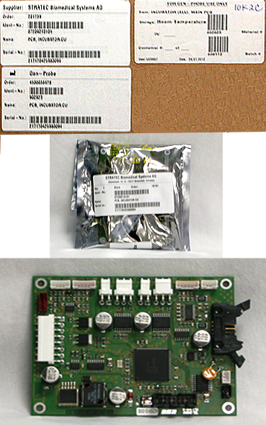