Incubator Carousel Motor Removal and Replacement

|
Note—This procedure applies to the Transition, High Temp, and Amplification Incubators. |
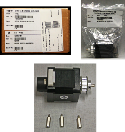
Parts and Materials Required
Time Required
Removal Procedure

|
MTUs may be present in module. It is necessary to remove all MTUs to avoid contamination. |
- Put on proper PPE.
- Remove the Incubator door assembly.
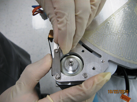
 Turn the Incubator upside down to access the three screws (A, B, and C) that secure the motor.
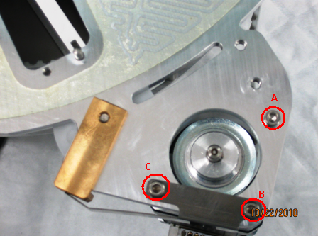
- Using a 2.5 mm hex key, remove the three screws.
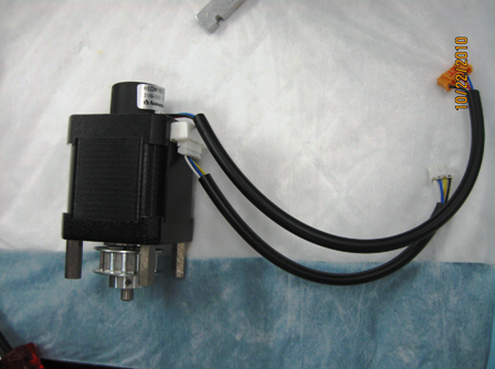
- Remove the motor.
Replacement Procedure
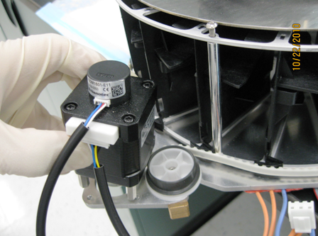
- Remove the three motor standoffs, motor cable, and motor encoder cable and transfer them to the new motor assembly. Ensure the three standoffs are installed in the three hole locations on the motor body as in the picture.
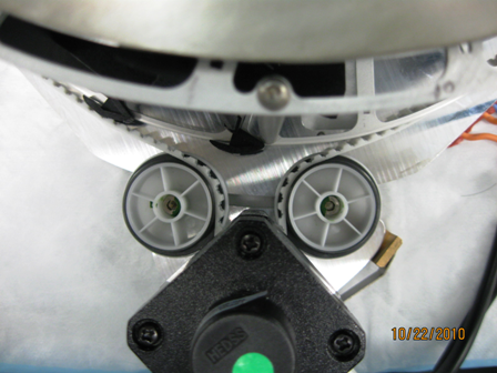
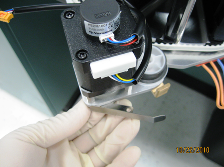
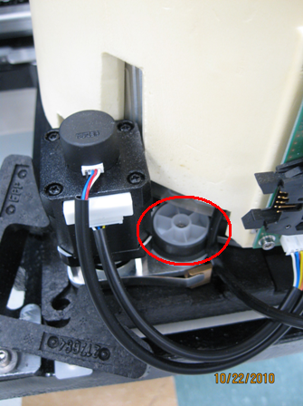
- With the Incubator assembly right side up, orient the belt, pulley bearings, and the motor.
- Replace and fasten screw A to the bottom plate.
- Fasten screw B to the bottom plate with the tensioner.
- While applying force to the tensioner, secure screw C.
- Verify that the carousel spins freely, and the belt is engaged to all teeth and gears.
- Reverse the removal procedure.
- Rinstall the Incubator.
- Perform a belt tensioning procedure.
- Open Service Software.
- Initialize the replaced Incubator and allow it to reach thermal equilibrium (15–30 minutes).
- Remove the motor insulation cover and raise the Incubator cover to expose the tensioner pulley.
- Using a 3 mm hex key, loosen the tensioner pulley and allow the assembly to auto-tension.
- Tighten the 3 mm screw.
- Re-install the motor insulation cover and reseat the Incubator cover.
Alignment/Calibration
- Perform an Incubator Slot Alignment procedure.
- Teach the Distributor to the Incubator.
- If this procedure was completed on an Amplification Incubator with RTFs, perform the RTF Alignment procedure.
Verification
- Perform a System Level Operational Qualification.
- Verify that the Incubator is within temperature specification.
Click the  button at the top of the page to send feedback, comments, or change requests.