Shave Foam Off Incubator Door
Parts and Materials Required
- Panther Tool Kit
- Proper PPE
Time Required
- 1 hour
Things to Remember
The AMP Incubator contains amplicon and designated a post-AMP (dirty) module. Referring to Biohazard Safety Information. follow safe lab practices during this procedure.
Procedure
|
|
WARNING—MTUs may be present in module. It is necessary to remove all MTUs to avoid contamination. |
- Put on proper PPE.
- Power on the Panther System.
- Power on the PC.
- Start Panther Main and allow system to initialize.
- Shutdown Panther Main.
- Power down the Panther System.
- Power down the PC.
- Visually confirm there are no MTUs in the incubator.
- Prepare a work surface:
- With 2.5%–3.5% sodium hypochlorite solution, spray a stable work surface.
- Wait 1 minute. (Do NOT allow sodium hypochlorite solution to dry)
- Wipe up the 2.5%–3.5% sodium hypochlorite solution.
- Wipe area with DI water and a towel.
- Lay clean absorbent bench pads on the cleaned area.
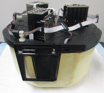
- Remove the Incubator referring to Incubator Module Removal and Replacement.

Note—Use extreme caution if you are removing the Amp Incubator, as there may be RTFs installed. The RTFs are not affected by this procedure so no RTF alignment or testing will be required.  Place the incubator upside down on the clean bench pad.
- Remove the door assembly from the incubator according to Incubator Door Assembly Removal and Replacement.
Note—Some incubators may have a door clip or a screw in the door frame to secure the incubator door (refer to Door Clip Inspection). In this case, remove the clip or screw before proceeding. - Disconnect the door assembly ribbon cable from the main Incubator PCB.
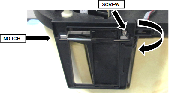
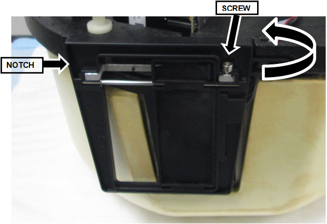
- Remove the 3 mm screw holding the door.
- Gently but firmly pull and rotate the door outward from the right to free the door.A notch on the left side holds the door in place.

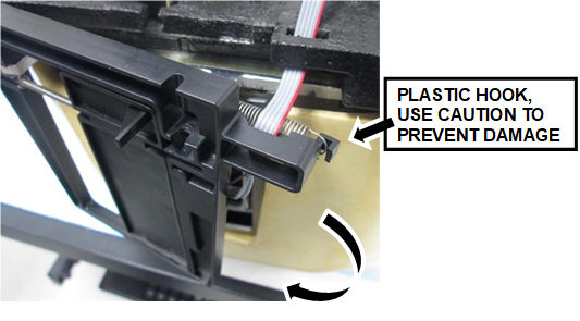
CAUTION—There is a plastic hook on the back of the door that holds one end of the spring. This hook clears the bottom foam when the door is rotated out, but use extreme caution to avoid any damage to the hook.
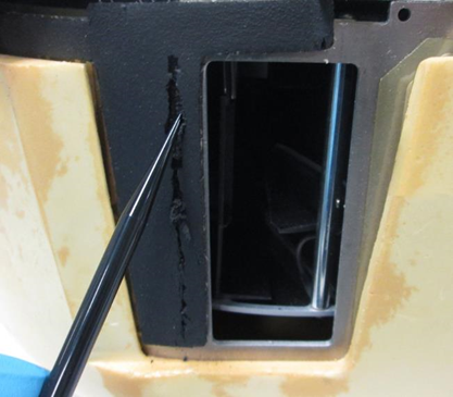
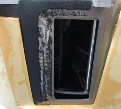
- Using a DiTi tip, trim the insulation foam back approximately 8–10 mm from the door as shown below.
(DO NOT use a utility knife or any sharp tool that may damage the heat sink) - The trimmed door foam should look like the picture below when complete.
- Reinstall the door assembly:
- Engage the notch on the left side of the door.
- Swing the right side into place.
- Press the door assembly into place.
- Using the 3 mm screw, secure the door.
- Reconnect the ribbon cable to the PCB.
- Check the incubator door opens and closes smoothly.
- If a door clip or screw is removed in Step 12, reinstall the screw.
- Reinstall the Incubator referring to Incubator Module Removal and Replacement.
Verification
- Ensure all Alignment Calibration/Verifcaiton steps pass after reinstalling the incubator module.
The Alignment/Calibration/Verification steps include: - Teach (align) the Distributor to the Incubator.
- Perform the Incubator Slot Alignment.
- Perform a Panther System Operational Qualification (OQ). Only select the replaced Incubator(s).
- Verify the Incubator is within temperature specification referring to Thermal Sensor Ranges for Aptima Assays.
- Verification is complete.
 button at the top of the page to send feedback, comments, or change requests.