Fusion Pipettor Removal and Replacement

|
Note—A Firmware Installation procedure must be performed when replacing a module or PCB. |
|
|
Note—
BLDC Pipettors can ONLY be installed with System Software v7.1 or higher. |
Parts and Materials Required
- FSE Tool Kit
- Bench Top Pads
- Fusion Pipettor (Right) or
- Vial Robot (TTA, Left)
Time Required
- 1 hour
Pipettor Removal Procedure
- Power down the Panther System and PC.
- Remove the Front (top) Canopy and open the Front Canopy Door.
- Place an absorbent pad over the Reaction Tube Tray and Tip Drawers to prevent any parts from falling into the system.
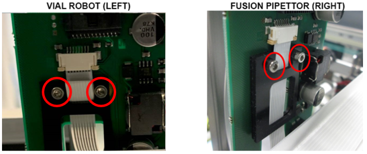
- Position the Pipettor arm to be replaced (Fusion Pipettor or Vial Robot) over the pad.
 Using a 2mm hex key, loosen (do not remove) the two screws that secure the flex cable strain relief bracket(s).
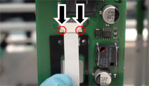
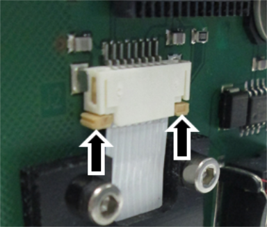
The Fusion Pipettor arm has two black strain relief brackets, while the Vial Robot has one.- Unlock the flex cable connector clamps by pressing down on the tabs as shown.
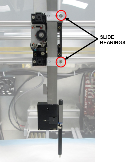
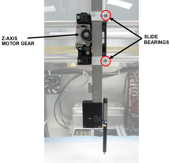
Then pull down gently to disconnect the flex cable from the Pipettor PCB. - While securely holding onto the Pipettor arm, remove both L-shaped slide bearings (2.5mm hex) and set aside.
Remove the arm.
Pipettor Replacement Procedure
|
|
Note—The Fusion X-axis belt procedure is identical to Panther with the exception of the belt length call-out. |
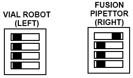
- Verify DIP switch settings.
- Set the arm in place against the Y-carriage and guide the pipettor teeth into the Z-axis motor gear.
- Secure the arm with the two L-shaped slide bearings as shown.
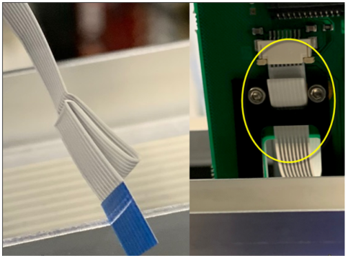
- Route the new flex cable through the strain relief brackets as shown.
- Connect the flex cable to the PCB and lock the flex cable connector clamps by pushing up on the tabs.
Make sure that the flex cable contacts are facing away from the PCB. - Tighten the screws on the strain relief bracket(s).
- Manually slide the Pipettor arm up and down and verify that the flex cable does not kink.
If necessary, adjust the flex cable to eliminate any kink. - Verify that the arm is securely in place and does not slide down when released.
Do not over-tighten any screws. - Perform the Z-Motor Meshing Adjustment Procedure.
IMPORTANT—Proper meshing is critical to pipettor operation.
Incorrect meshing can lead to dropped consumables and failed aspiration.

Verification
- Power on the Panther System and PC.
- Install Panther Fusion System firmware to the module.
Refer to Panther Fusion System Installation > Run Instrument Setup (Fusion). - Refer to the Service Procedures section and perform the following:
- Panther Fusion System Pipettor Teaching
- Fusion Pipettor Pressure Integrity Test - For Fusion Pipettor (Right) Arm Only.
- Fusion Pipettor cLLD and bLLD Test
- Side Car Pipettor OQ Test
 button at the top of the page to send feedback, comments, or change requests.