Solid Waste on the Fly Installation

This procedure will install the following hardware:

  1. ClosedY-Splitter CAN Cable

  2. ClosedTip Carousel
  3. ClosedTipletClosedDisposable tip within an MTU. Catcher

Parts and Materials Required

  • Panther Tool Kit
  • Continuous Access Parts Kit
  • High Vacuum Grease

Procedure

  1. Power down the Panther System.
  2. Power down the PC.
  3. Closed
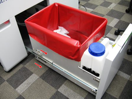
Remove the Waste Drawer Cover
    1. ClosedSlide the Waste Drawer open as far as possible.
    2. Safely remove and discard the solid waste.
    3. Remove the Waste Bottle, discard the liquid waste and set the bottle aside.
    4. ClosedUsing a 3 mm Allen wrench, remove the 2 screws from the left side of the Waste Drawer.
    5. ClosedUsing a 3 mm Allen wrench, remove the 2 screws from the right side of the Waste Drawer.
    6. ClosedRemove the screw that secures the Waste Drawer front cover panel to the bracket.
    7. ClosedRemove the front cover panel from the Waste Drawer.
  4. Closed
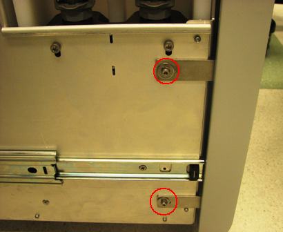
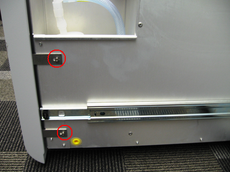
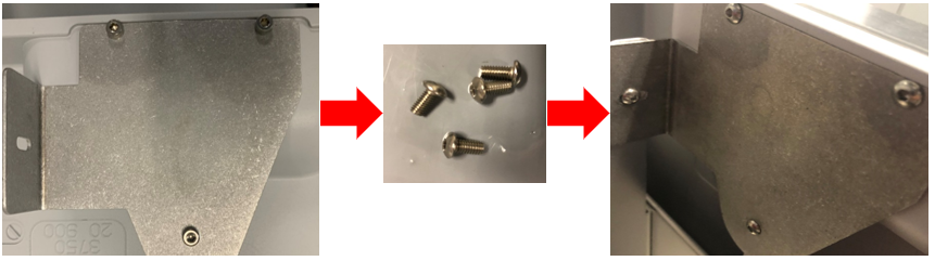
Replace Waste Drawer Front Cover Panel Screws (from SHCS to Button Head)
    1. Remove the screws that secures the Waste Drawer front cover panel to the bracket.
    2. ClosedReplace the bracket mounting screws with button head style screws and set the cover aside as needed.

  5. Remove the Marketing Panel
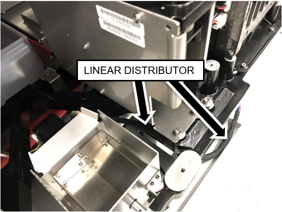
  6. Remove the Linear Distributor.
  7. Remove the Magnetic Parking Station.
  8. Remove the Reagent Tip Chute.
    Note— After removing the Reagent Tip Chute, save the 2 mounting screws for reassembly. Dispose of the 2 large OD washers.
  9. Remove the Sample Dispense Slot.
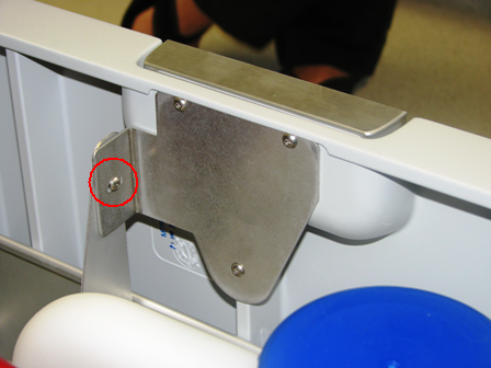
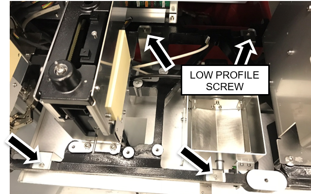
  10.  Unclip the cable harness clamps on the Splash Shield.
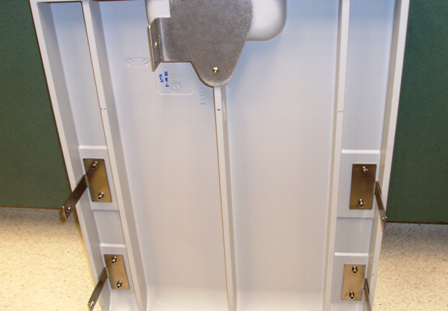
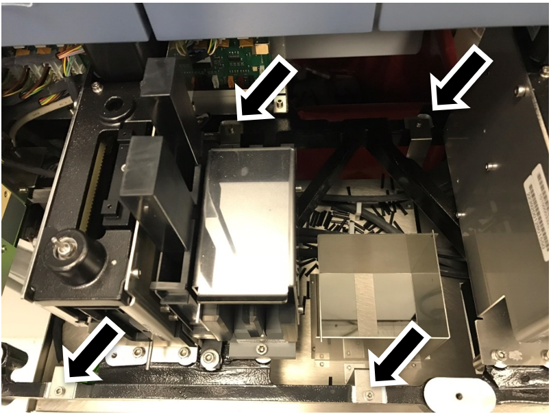
    Note—Review the routing of the cables. Take a picture if this is helpful. Similar routing will be required with new Tiplet Catcher module.
  11. ClosedRemove the four Splash Shield mounting screws. Save the screws for reassembly.

  12. Remove the existing Splash Shield.
  13. Closed
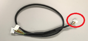
Install the Y-Splitter CAN cable.
    1. Disconnect and remove the Chiller CAN cable from the system.
      Note the location of the connector on the COP2 PCB.
      This will be the location for the origin connector on the new Y-splitter CAN cable.
    2. Plug the origin of the of the Y-Splitter into the open CAN location on COP2 .
      (where the Chiller CAN cable was previously connected).
      Note—If there is an open location on a COP2 board, the downstream modules will not connect. The last connection of the COP2 board is reserved for the bridge to the Main COP.
    3. Connect the longer end of the Y-Splitter to the Chiller.
    4. The shorter end of the Y-Splitter connects to the Tip Carousel (installed later in this procedure).
    5. ClosedRoute both branches of the Y CAN cable behind the HPAClosedHybridization protection assay—The Hologic HPA technique uses a specific DNA probe, labeled with an acridinium ester detector molecule that emits a chemiluminescent signal. Load Station as shown below then follow the previous routing to the Chiller.

  14. Re-install the Sample Dispense Slot.
  15. Closed
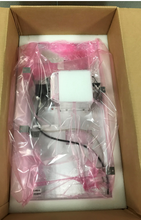
Remove all packing foam from the Tiplet Catcher.

  16. ClosedInstall the Tiplet Catcher.
    1. Position the Tiplet Catcher in the same mounting location as the Splash Shield.
    2. ClosedSecure the Tiplet Catcher to the drawer using the four mounting screws that were removed from the Splash Shield.
      Note—Use the low-profile screw in the back right position.

    3. Route the CAN cables behind and below the Tiplet Catcher motor.
      Note— Ensure that the Tiplet catcher motor and sensor cables are above the CAN cables.
      1. ClosedSecure the cables using the cable clamps.

      2. Route the Tiplet Catcher motor and sensor cables through the triangular opening in the drawer frame as shown above.
      3. ClosedEnsure the Linear Distributor cable is routed as shown.

  17. ClosedPrepare the Tip Carousel for installation.
    1. ClosedLoosen the two screws securing the PCB cover and set the cover aside.

    2. ClosedEnsure DIP Switch 1 on the Tip Carousel PCBA is set to 1 ON, all other Switches are OFF.

    3. ClosedManually move the tip holders to inside the Tip Carousel Storage area.
      This is to reduce damage to the tip holders during installation.
  18. Closed
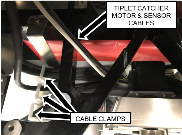
Secure the Tiplet Catcher motor and sensor cables through the cable clamp on the tip carousel.
  19. Closed
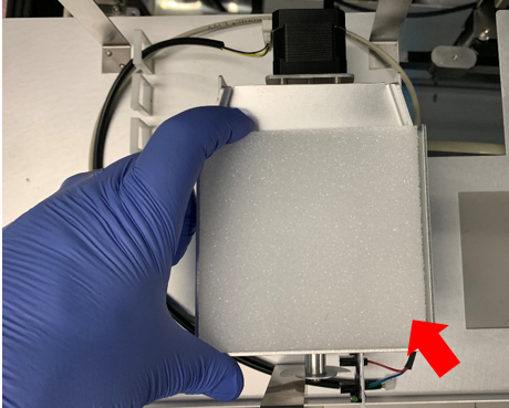
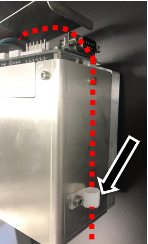
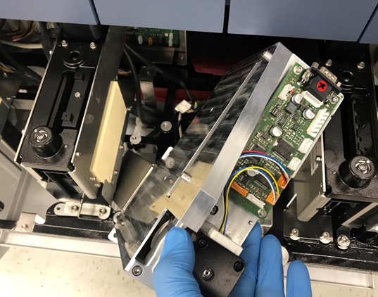
Insert the Tip Carousel into the location previously occupied by the Reagent Tip Chute at the angle shown below.
    The Reagent Tip Chute will be secured in a later step.
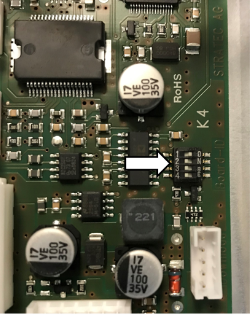
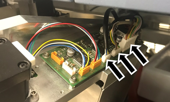
    Note—Do NOT screw down the Tip Carousel yet.

  20. ClosedConnect the CAN cable, motor cable, and sensor cable to the Tip Carousel PCB.
    The shorter end of the Y-Splitter CAN Cable connects to the Tip Carousel
    Note— Ensure that the Tiplet catcher motor and sensor cables are to the left of the CAN cable.

  21. Secure the Tip Carousel to the drawer frame using the screws from the Tip Chute.
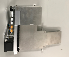
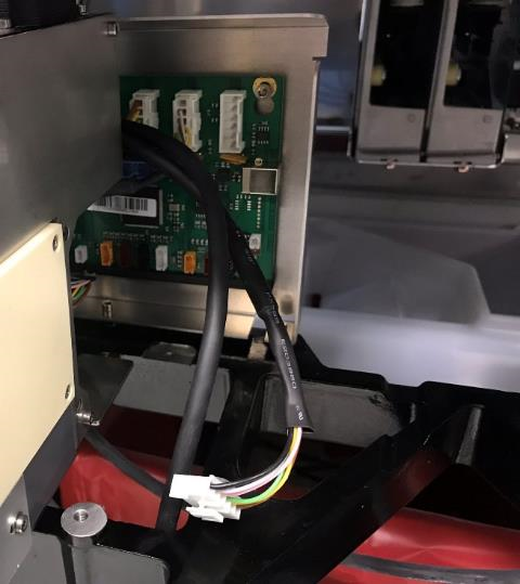
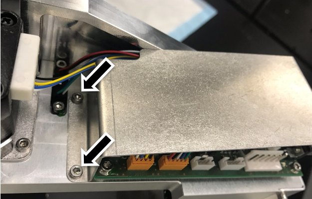
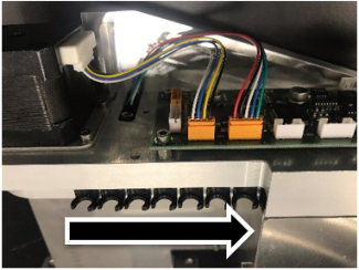
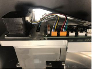
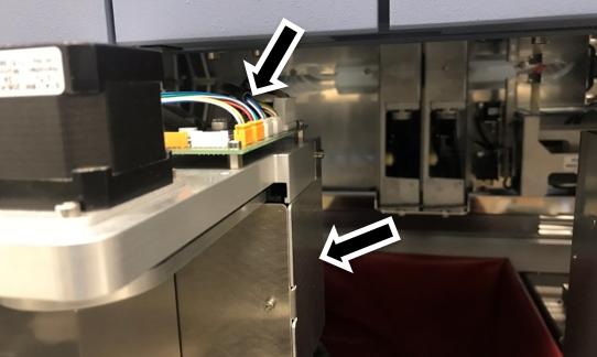
    DO NOT use the washers. A long handle ball-end 4mm hex driver is required to tighten the rear screw.
  22. ClosedEnsure the cables do not protrude too high above the PCBA (arrow in figure below).
    Ensure the cables do not protrude too far outside the rear right side (arrow in figure below).
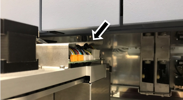
    Note—Improper routing may result in damage to the cables when closing the service drawers.

  23. ClosedRe-install the Tip Carousel PCBA cover. Make sure the cover maintains clearance from the PEM nuts on the frame above.

  24. Closed
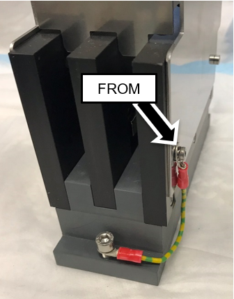
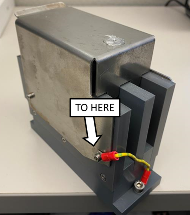
Move the grounding wire of the Magnetic Parking Station from the right side of the module (when viewed from the rear) to the left side of the module using the existing screws. The lug barrel must be oriented as shown below to maintain clearance with the Mag Wash when the service drawer is closed.
  25. Re-install the Magnetic Parking Station.
    Note—ClosedEnsure the grounding wire is routed tightly against the side of the Parking Station and tucked in behind the module, so it does not catch on the Magnetic Wash Station when the service drawer is closed.

  26. Re-install the Panther Linear Distributor.
  27. Continue to install either:
    1. GRIFOLS ONLY - LWOTF, Existing Waste Drawer Upgrade
    2. LWOTF, New Complete Waste Drawer Installation