GRIFOLS ONLY - LWOTF, Existing Waste Drawer Upgrade

This procedure will install the following hardware:

Parts and Materials Required

  • Panther Tool Kit
  • Sharpie
  • Wire/Cable Cutter
  • Tubing Cutter
  • Continuous Access Parts Kit
  • Vacuum Grease

Procedure

  1. Closed
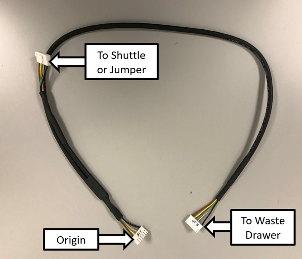
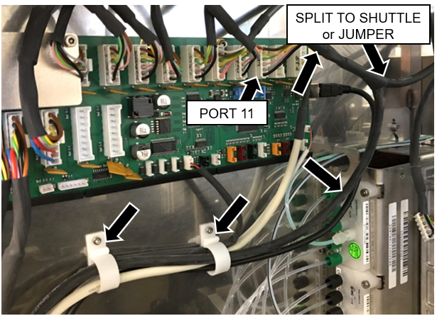
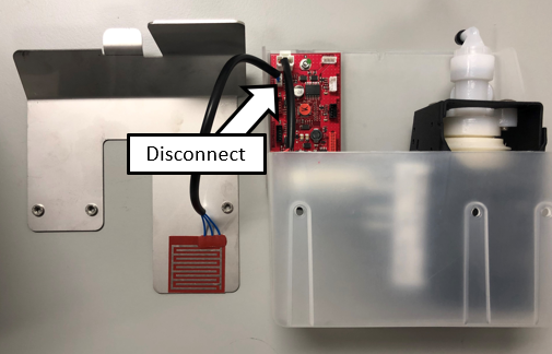
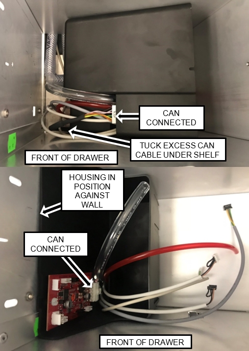
Connect the CAN Cable
    1. Power down the Panther System.
    2. Power down the PC
    3. Remove the left side door and set aside.
    4. Disconnect the ACClosedAlternating current Power Cable from the switch panel.
    5. ClosedConnect the Y-Splitter CAN Cable
      1. Take the Y-splitter cable and connect the origin to the next open port on the Main COP.
        The next open Port in most systems will be Port 11.
        Note—If a jumper is installed in Port 11, move the jumper to Port 12 and connect the Origin to Port 11.
      2. If this Panther is connected to a Track, route the short branch of the CAN cable to the Shuttle.
      3. ClosedIf the Panther will NOT be connected to a Track, install a Jumper and Extension adapter to the Short End of the Y-Splitter CAN Cable.
      4. ClosedRoute the Long CAN Cable branch from the COP to the Waste Drawer area along the left rear corner of the vertical chassis as shown below. Use the existing cable clamps and route the cable behind the cooling line.
        Note—Open the Service Drawer for easier access to route the cables

      5. Leave the end of the cable in the Waste Drawer area - it will be routed into the Waste Drawer and connected in a later step.
  2. ClosedPrep the Waste Drawer
    1. ClosedSlide the Waste Drawer open as far as possible.
    2. Safely remove and discard the solid waste.
    3. Remove the Waste Bottle, discard the liquid waste and set the bottle aside.
    4. ClosedRemove the Waste Drawer Cover and set aside
        1. ClosedUsing a 3 mm Allen wrench, remove the 2 screws from the left side of the Waste Drawer.
        2. ClosedUsing a 3 mm Allen wrench, remove the 2 screws from the right side of the Waste Drawer.
        3. ClosedRemove the screw that secures the Waste Drawer front cover panel to the bracket.
        4. ClosedRemove the front cover panel from the Waste Drawer.
        5. Note—Save all screws for reassembly
        6. Closed !!! IMPORTANT!!!
          Replace the bracket mounting screws with button head style screws and set the cover aside as needed.
  3. ClosedTubing and Cable Installation and Routing
    1. Closed
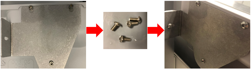
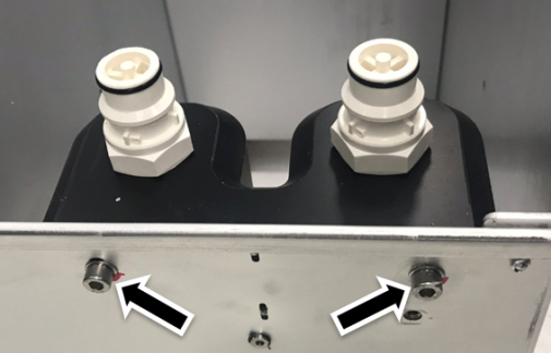
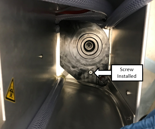
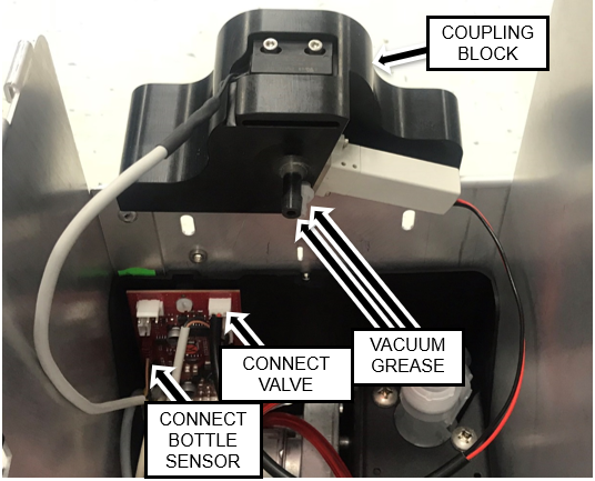
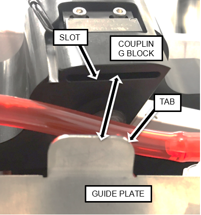
Remove the Waste Bottle Coupling Block with a 4 mm Allen key.
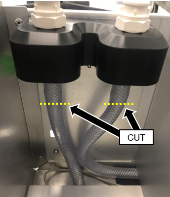
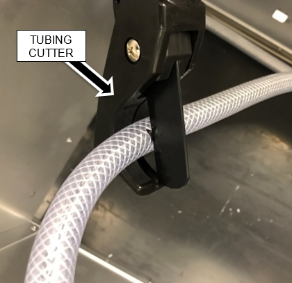
      Note—Save screws and washers for reassembly.
    2. ClosedCut the two pieces of vacuum tubing just below the Waste Bottle Coupling Block fittings with a tubing cutter. Discard the Coupling Block.

    3. Closed
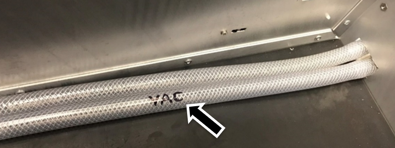
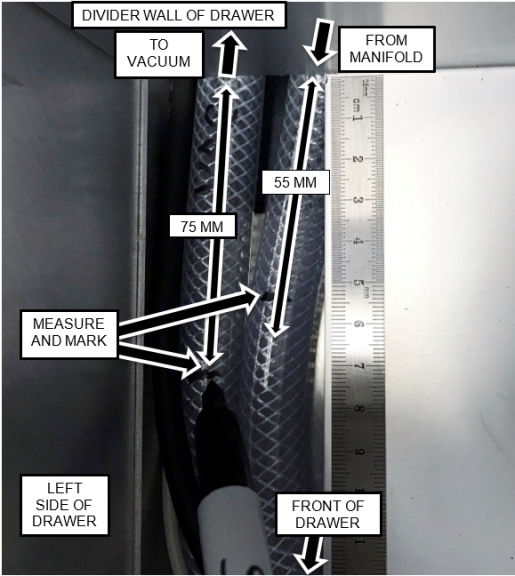
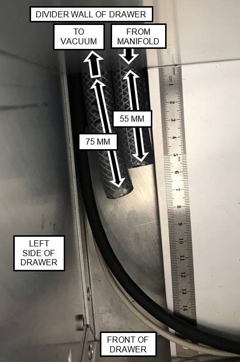
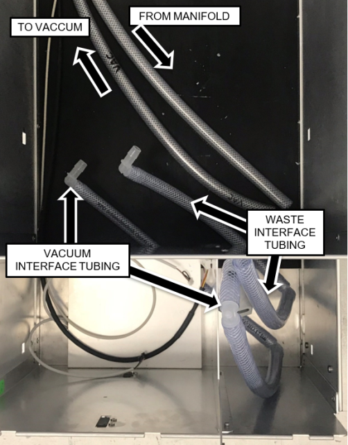
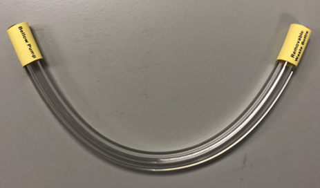
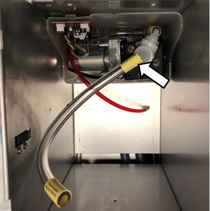
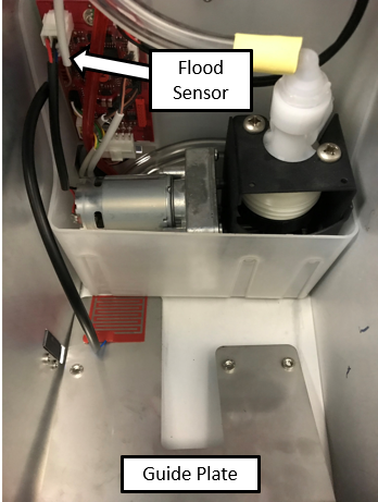
Label the vacuum flow return tubing in the Solid Waste Bag area as shown.
      Note—Label the tubing that is routed to the filter.
      This vacuum line will be used to connect the new vacuum filter.

    4. Remove and dispose of the vacuum filter.
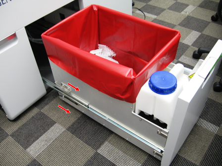
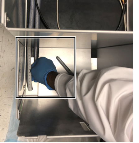
    5. Place enough blue pads to cover the floor below the Waste Drawer.
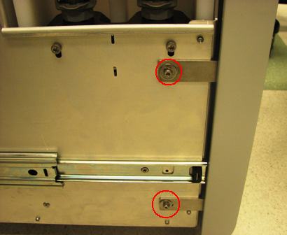
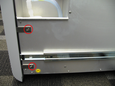
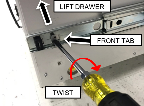
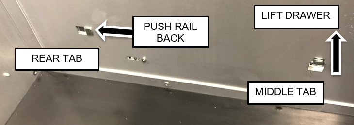
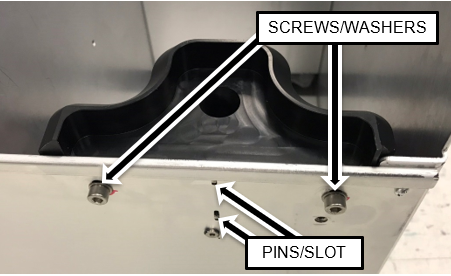
    6. Remove the Waste Drawer from each of the drawer rails.
      Closed Pull the drawer up to free it from the forward two tabs and slide the drawer rail back to free if from the rear tab.
      Note—To assist in lifting the front of the drawer off the front tab, insert a flat blade screwdriver below the lower edge of the tab and twist while pulling up on the drawer as shown below.

    7. Turn the Waste Drawer on its right side to access the bottom of the drawer.
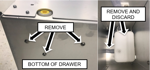
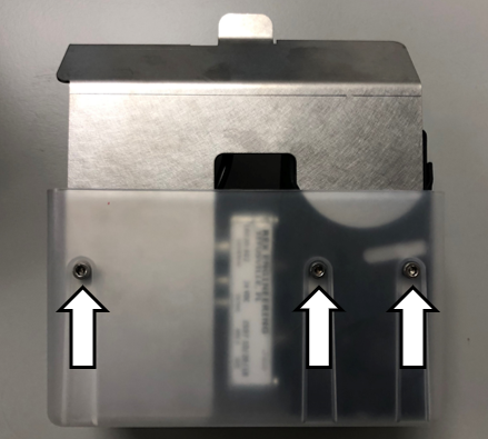
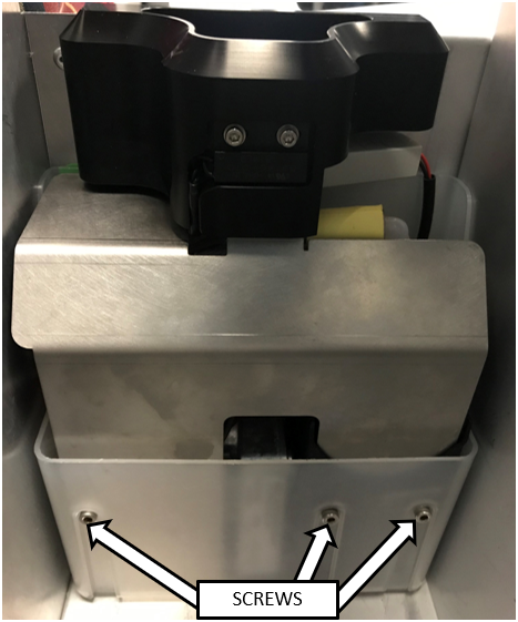
    8. Remove the Coalescing Trap
      ClosedUse a Phillips screwdriver to remove the three screws securing the coalescing trap to the bottom of the drawer.

    9. Remove and discard the coalescing trap along with the connected tubing.
    10. Closed
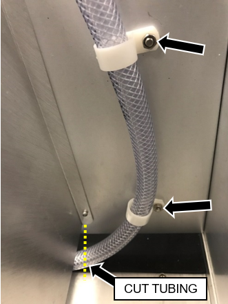
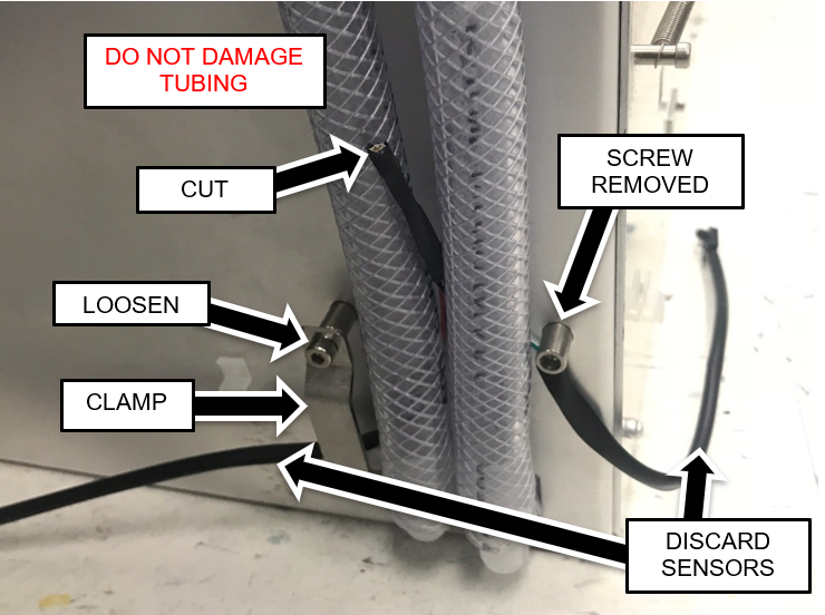
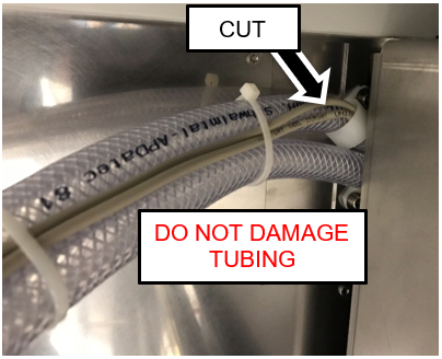
Cut the vacuum line tubing near the dividing wall, as shown below.

    11. Remove the nuts securing the tubing clamps that hold the vacuum line to the filter area in the front of the waste drawer.
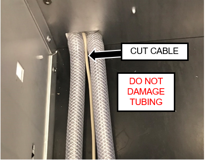
      Note—Dispose of the clamps and tubing but retain the nuts.
    12. ClosedCut the cable for the waste bottle full and empty float sensors near where it exits the drawer with a wire cutter.
      Caution—DO NOT damage the tubing.
    13. ClosedRemove and retain the four screws securing the empty and full sensors to the front of the drawer.
      Remove and discard the sensors along with the cut cable.

    14. Closed
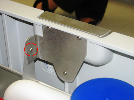
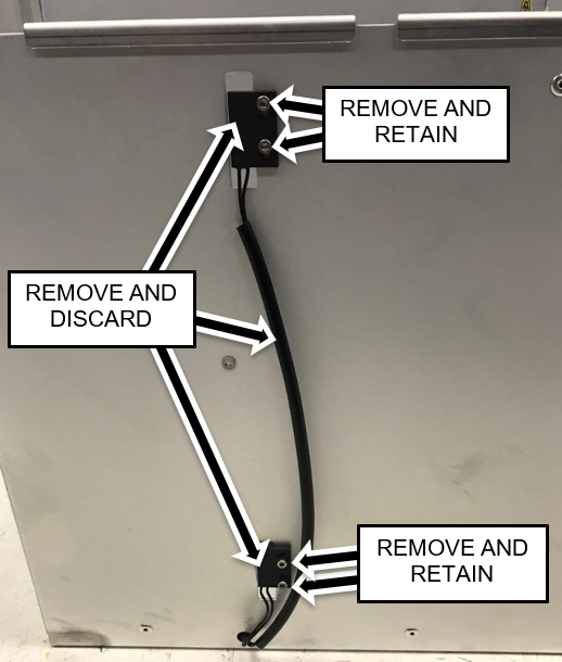
Remove and retain one of the screws securing the lower tubing clamp to the standoffs on the back of the drawer. Loosen the other screw and move the clamp aside.

    15. Closed
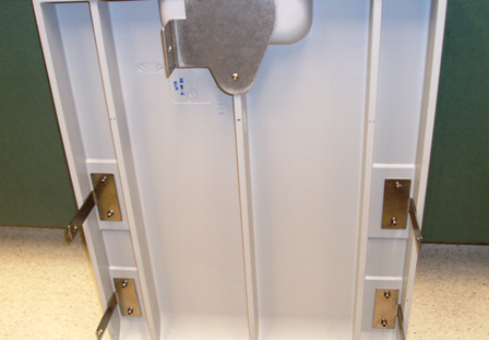
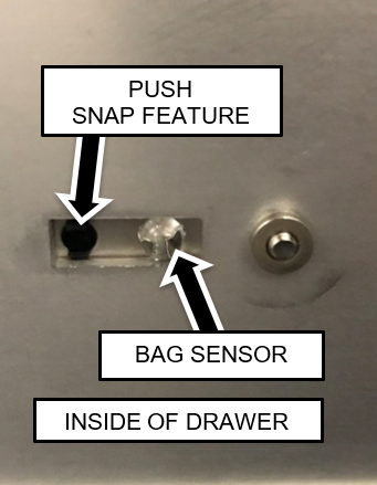
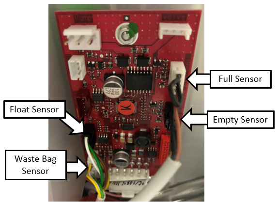
Remove the two waste bag presence sensors from their mounting plates.
      Push the snap features from the inside of the drawer using a small Allen key if necessary.

    16. ClosedUnclip the cables from the harness clamps on the sides and back of the drawer.
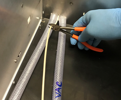
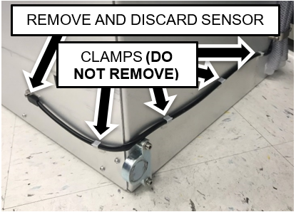
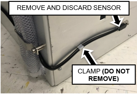
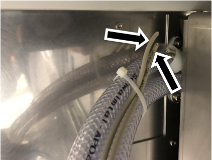
      Note—Do not remove the cable clamps from the sides of the drawer.
    17. ClosedCut the two sensor cables (Waste Bag Presence and Waste Bottle Full/Empty) near their cable clamp as shown below. The sensor cables are located behind the vacuum housing in the rear of the lower chassis.
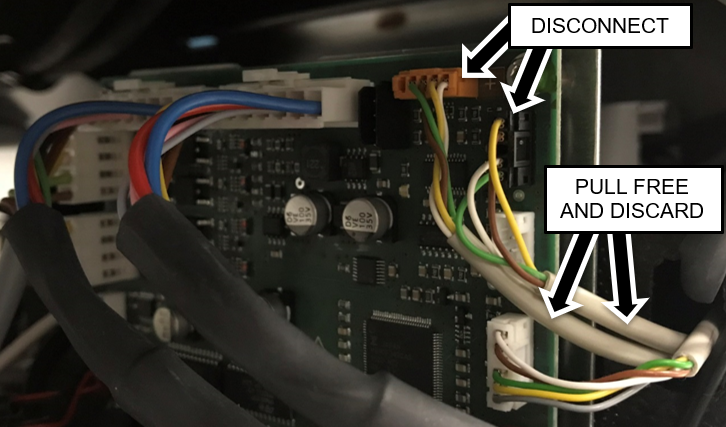
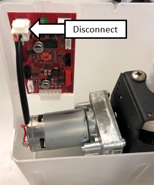
      Caution—Be careful not to damage the vacuum tubing.
    18. ClosedDisconnect the waste bag and bottle sensors from the Cooling Module PCB.
      Pull cables from behind Vacuum and Cooling Module.
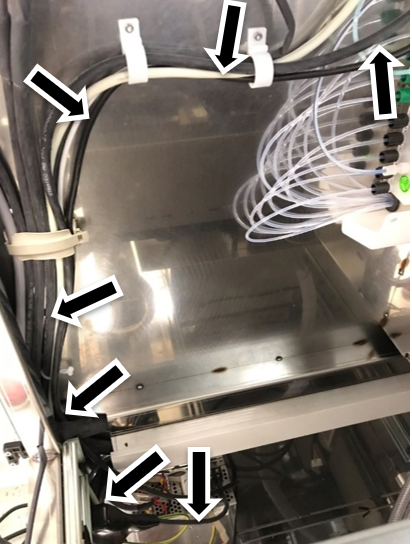
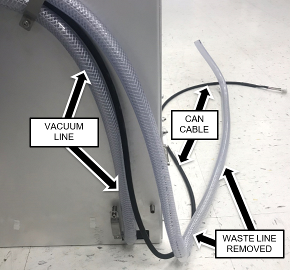
      Note—For easier access open the Universal Fluids Drawer, unlatch the Vacuum Module and slide it forward to allow the cables to be pulled free.

    19. ClosedRoute the new CAN cable.
      1. Starting near the back-chassis panel and work progressively forward one section at a time.
        Start the CAN cable routing approximately 1 ft (30 cm) from where the tubing is clamped to the back-chassis panel.
        Note—Cut and discard existing zip ties where necessary and replace with new zip ties. For systems with the spiral cable wrap, complete the cable replacement on the rear half first before replacing the cables in the front half
        Note— The Images below show routing with a spiral wrap. On some systems the Spiral Wrap may prevent the Waste Drawer from locking.
        Zip Ties can be used in place of Spiral Wrap to secure and route tubing and cables

    20. Remove and retain one of the screws securing the upper tubing clamp.
    21. Loosen the other screw and move the clamp aside.
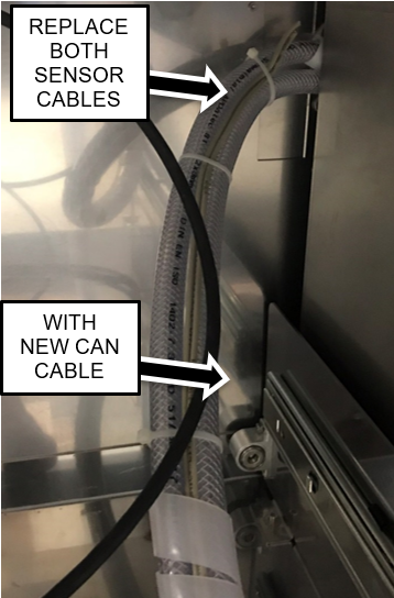
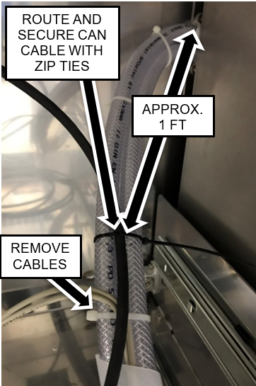
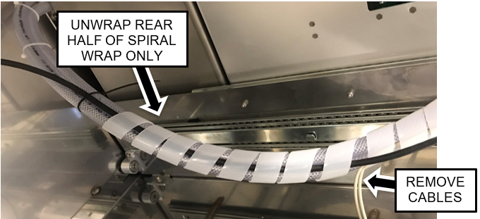
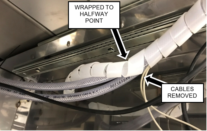
      Caution—Be careful to maintain the original positions of the tubing.
    22. Remove the remaining section of sensor cables.
    23. Closed
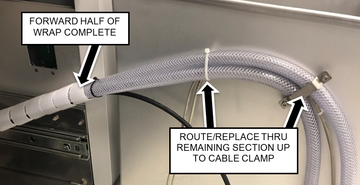
Route the new CAN cable behind and between the tubing and reattach the tubing clamp.

    24. ClosedPull the waste line tubing (from the Waste Bottle Block) completely out of the drawer.
      Leave the vacuum tubing in the drawer.
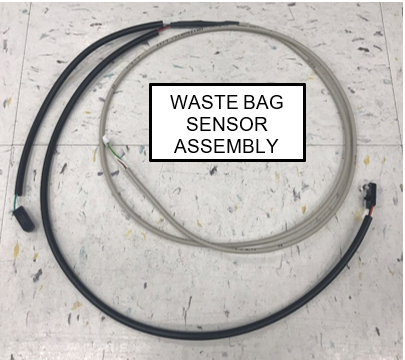
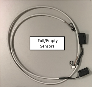
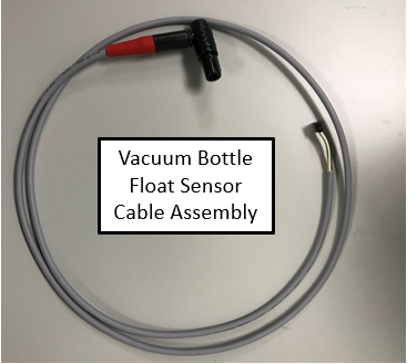
      Note—The lower cable clamp should still be moved aside from a previous step.

    25. ClosedInstall the new Waste Bottle Sensor Cable.
      The short branch routes to the left side of the drawer and the long branch is on the right side (as you face the system).
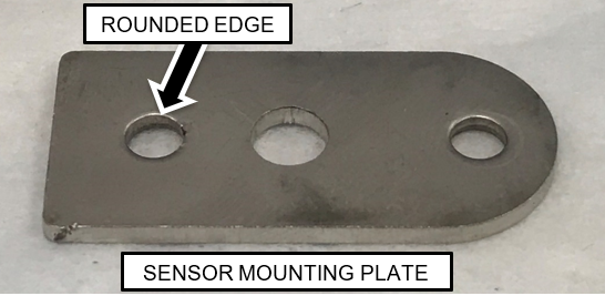
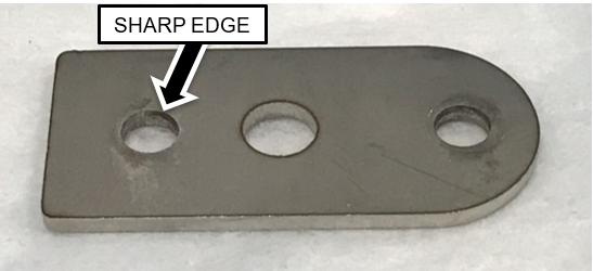
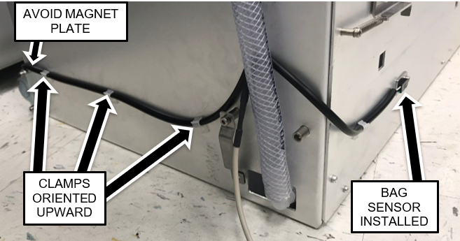
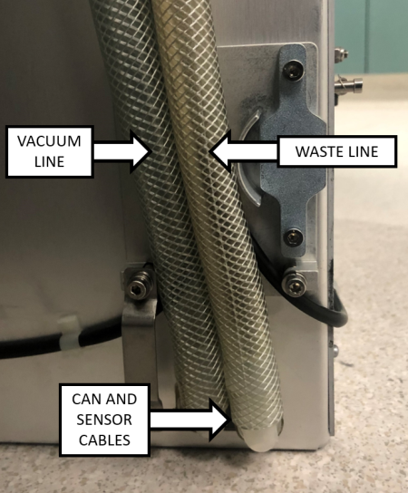
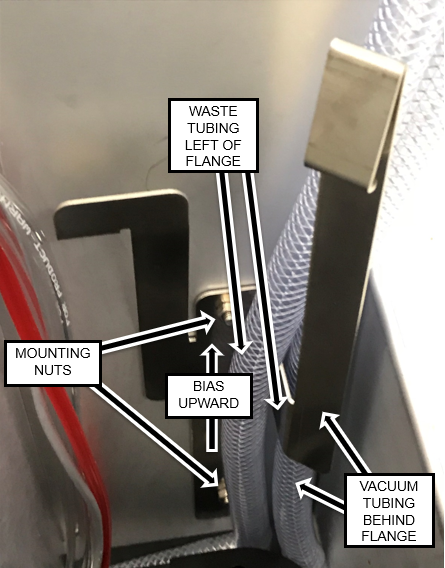
      Note—The sensor modules have snap features that press into a hole in the sensor mounting plates. One side of the mounting plate will have a slightly more rounded edge than the other. The snap is pressed in from the side with the more rounded edge.
    26. ClosedRoute the branches of the cables behind the drawer and position the cable behind the vacuum tubing as shown.

    27. Secure the cable to the sides of the drawer with the cable clamps oriented upward as shown above.
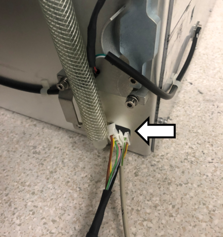
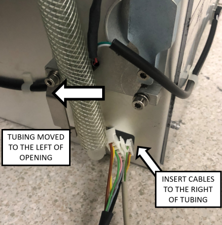
      Route the right-side of the branch such that it will not interfere with the magnet interface block as shown above.
    28. ClosedRoute the CAN cable through the opening in the drawer to the right of the vacuum tubing.

    29. ClosedRoute the Waste Bag Sensor Cable through the same opening.

    30. Pull up the cable slack such that the main branch of the cable enters through the opening. This will ensure that the outer jacket protects the cable at the edge of the opening.
    31. Closed
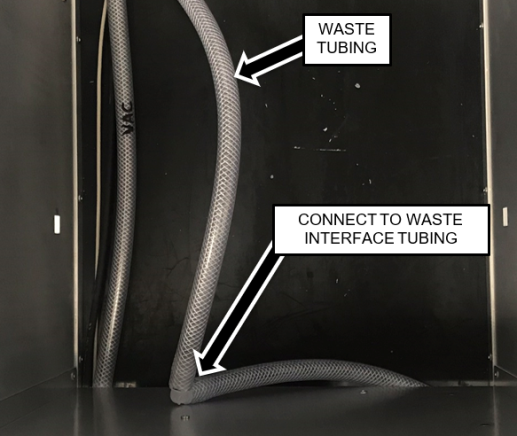
Insert the Waste Line tubing back into the drawer biased to the right side (when viewed from the rear).
      The Vacuum line should be on the left and Waste line on the right (when viewed from the rear).
    32. Re-attach the metal tubing clamp.
    33. Closed
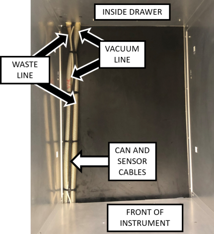
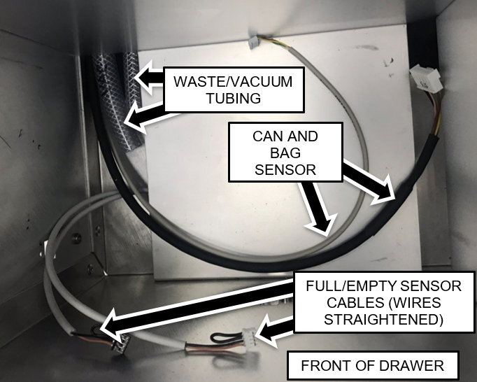
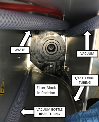
Inside the Waste Drawer, crisscross the vacuum tubing over the waste tubing as shown in the image below.

    34. Closed
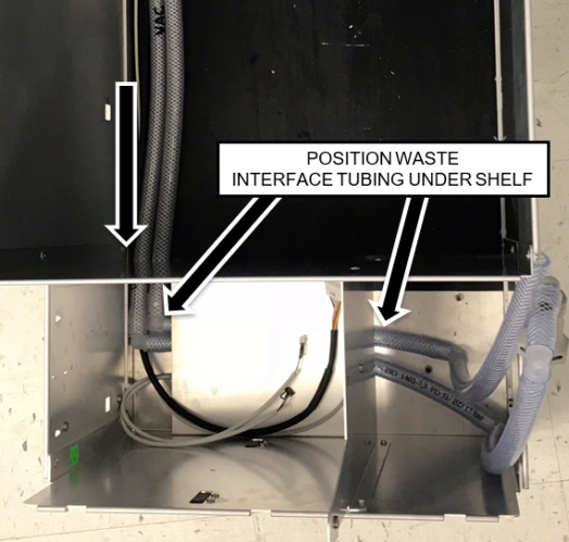
Position the tubing inside the drawer so that the ends are in the front left compartment of the Waste Drawer.
      1. ClosedMeasure and mark the vacuum line so that it extends 75 mm past the divider wall as shown.
      2. ClosedMeasure and mark the waste line (coming from the vacuum manifold) so that it extends 55 mm past the divider wall as shown.
      3. Mark the two pieces of tubing to the correct lengths as measured from the divider wall that separates the solid waste (Waste Bag) area from the liquid waste (Bottle) area.
        Note—The vacuum line should be closest to the left side of the drawer. It may be easiest to cut off some of the excess tubing, so that they can lie flat to do the measurements.
      4. ClosedAfter verifying the tubing orientations and lengths, cut the tubing with a tubing cutter such that the ends are square.
        Note—It is easier to measure and mark the tubing and then pull it into the Waste Bag compartment to be cut.

    35. Closed
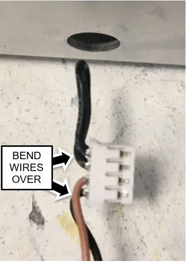
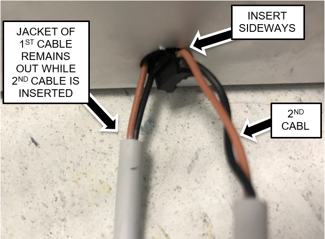
Prepare the Bottle Full and Empty Sensor Assembly to be installed by bending the wires at the connector as shown.
    36. Closed
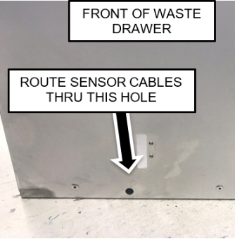
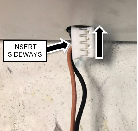
Insert ONE CONNECTOR AT A TIME into the hole in the front of the Waste Drawer.
      Note—The connectors must be oriented sideways to insert them into the hole. Do NOT insert the cable fully until the second connector is inserted.
    37. ClosedRoute the Full/Empty Sensors to the front left corner of the Waste Drawer as shown.
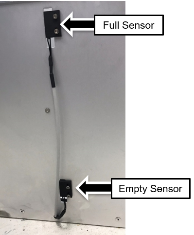
      Straighten the sensor wires that were bent in the previous step.

    38. ClosedAttach the Full and Empty Sensors to the front of the Waste Drawer.
      Use the screws removed from the original sensors. The sensor with the longer cable is the upper (Full) sensor.

  4. ClosedInstalling Tubing and Cables for Filter and Permanent Waste Bottle
    1. ClosedIdentify the Waste and Vacuum Interface Tubing assemblies as shown below.
    2. ClosedPosition the Interface Tubes so that the tubing ends in the front right area of the Waste Drawer and the barbed elbow fitting are in the Solid Waste Bag area as shown below.
      Note—The vacuum Interface Tubing assembly (with the quick disconnect fitting) should be more toward the front of the Waste Drawer as shown.

    3. Apply vacuum grease to the outside surface of the barbed fitting on the Vacuum interface tubing and fully insert it into the Vacuum line tubing.
    4. ClosedPosition the Interface tubing under the bottle shelf in the front of the drawer as shown.
    5. Apply vacuum grease to the outside of the barber fitting on the Waste Interface tubing and fully insert it into the Waste Line tubing.
    6. ClosedPosition the Interface tubing under the bottle shelf in the front of the drawer as shown.
    7. ClosedRoute the 1/4" ID Flexible Tubing, the 3 mm (1/8") flexible tubing, and the Vacuum Bottle Float Sensor Cable assembly under the shelf as shown.
      1. The larger right-angle connector of the cable should be on the right side of the drawer.
      2. Leave approximately 1 Foot (30-33 cm) of each tubing and the cable extending out of the left side
        (this can be adjusted later).
      3. Flexible tubing should have approximately 5" slack above the top.
    8. ClosedApply vacuum grease to the outside surface of the barbed fitting on the Filter Block and insert it into the vacuum bottle riser tubing.
      Note—Support the right-angle fitting with one hand while installing the tubing onto the fitting to ensure the fitting doesn't break.
      The tubing should be installed at least past the barb feature but leave approximately 2-3 mm of gap between the end of the tubing and the stop rib feature on the fitting.

    9. Apply vacuum grease onto the two O-rings on the filter block guide posts.
    10. ClosedPrepare to install the Filter Block by positioning the tubing in the locations shown below.
    11. ClosedLower the Filter Block into position as shown.
      Note—It may be helpful to move the waste tubing over into the Solid Waste Bag area, which will allow access to position the vacuum line into the Filter Block's slot by reaching underneath the drawer divider.
    12. ClosedWhen the Filter Block is in position, align the screw in the Block with the standoff in the bottom of the drawer and push the Block down until the Block is against the bottom of the drawer.
      Note—Full seating of the block can be verified by viewing the block through the gap at the bottom of the divider wall from the left side.
      The Block bottom surface should be mated against the bottom of the drawer as shown.

    13. ClosedSecure the Filter Block to the bottom of the drawer with the long screw included in the kit with a 4 mm Allen key.

    14. ClosedRoute the Waste Line, 1/8", 1/4", and Float sensor after installing the block.

    15. ClosedInstall the Filter retainer bracket as shown.
      Use an 8 mm wrench or socket to secure in place with the nuts originally used to secure the tubing clamps in this location. Bias the bracket as far upward as possible.

  5. ClosedInstalling the Permanent Waste Bottle and GAC Filter
    1. Closed
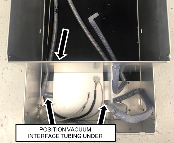
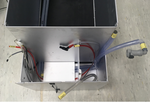
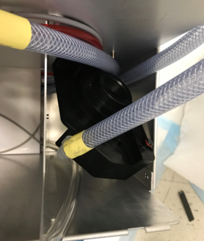
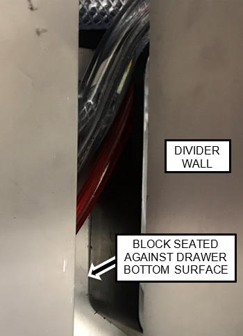
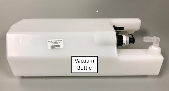
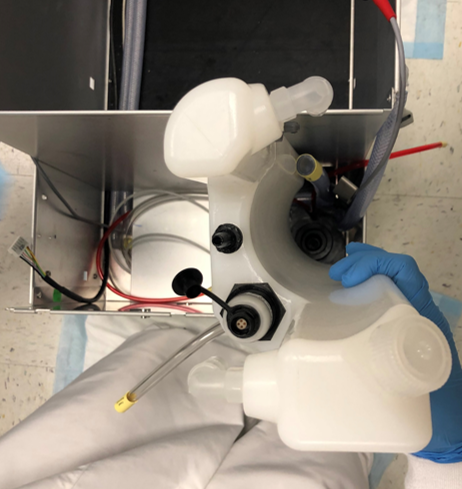
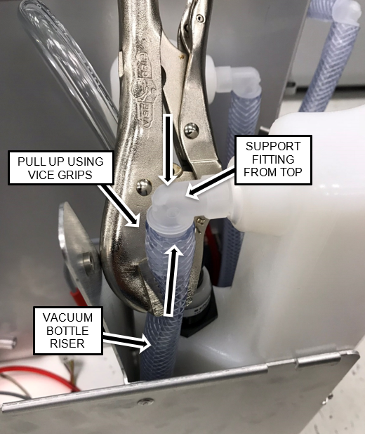
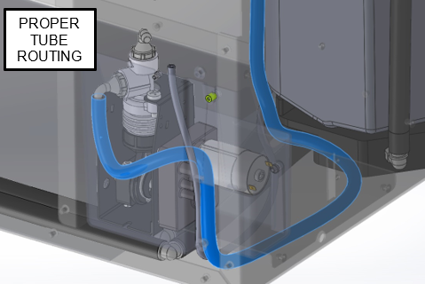
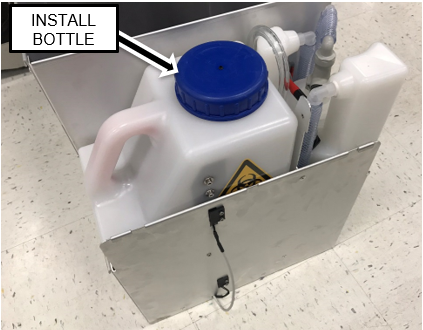
Slide the Vacuum Bottle into position while positioning the tubing and cables as shown.
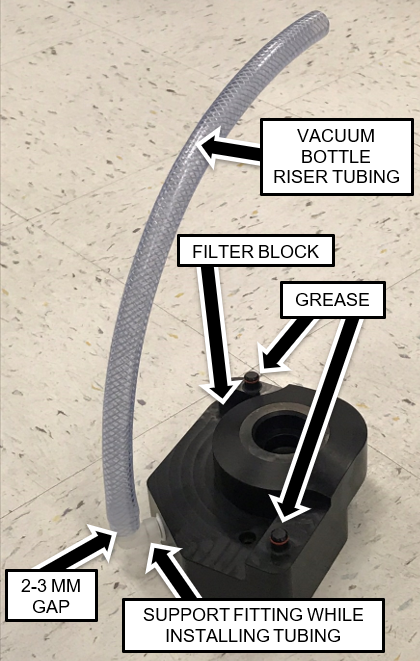
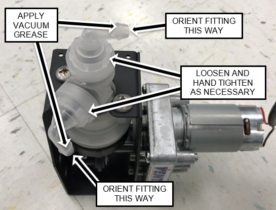
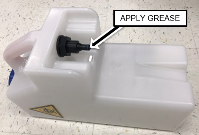
    2. Apply vacuum grease to both the large barbed fittings on the outside of the fixed/permanent vacuum bottle.
    3. Closed
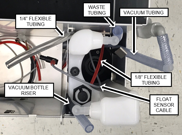
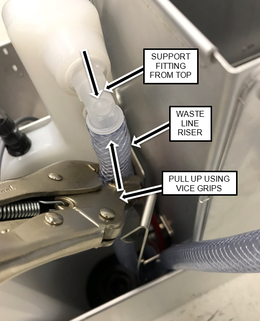
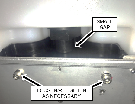
Install the Vacuum Bottle Riser and Waste Bottle Line Riser onto their respective fittings.
      Use a pair of vice grips to hold the tubing near the fittings while pulling up on the tubing.
      There should be no more than a 3mm gap between the tubing and flange.
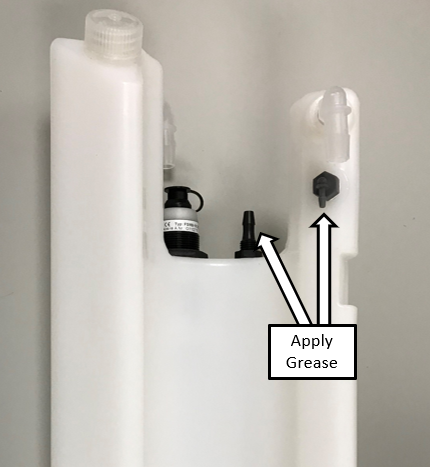
      Be Patient! Be Diligent!

      Caution—To avoid breaking the fittings, support the right-angle fittings from the opposite side with one hand while pulling the tubing onto the fittings.
      Note—On some installs the Interface tubing going to the permanent waste bottle may need to be trimmed.
    4. ClosedApply vacuum grease to the outside surface of the one small and one medium sized barbed fittings on the Vacuum Bottle.

    5. Closed
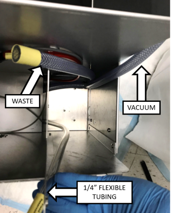
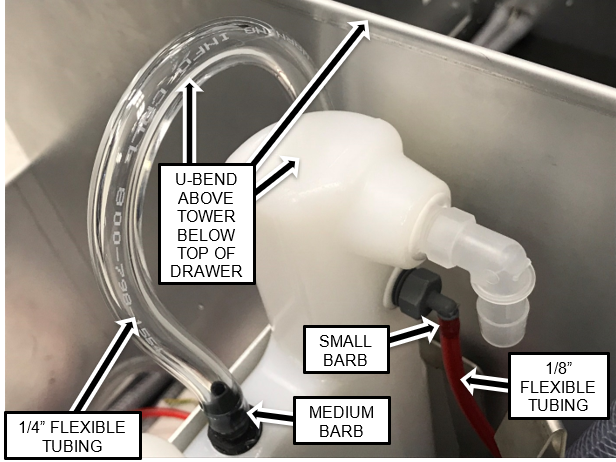
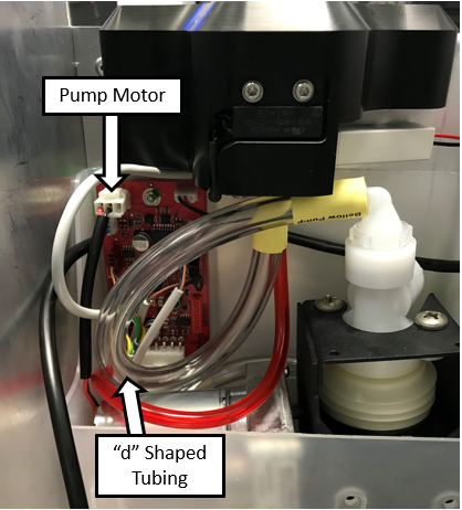
Install the 1/4" flexible tubing on the medium sized barbed fitting and the 1/8" flexible tubing onto the small sized barbed fitting.
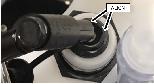
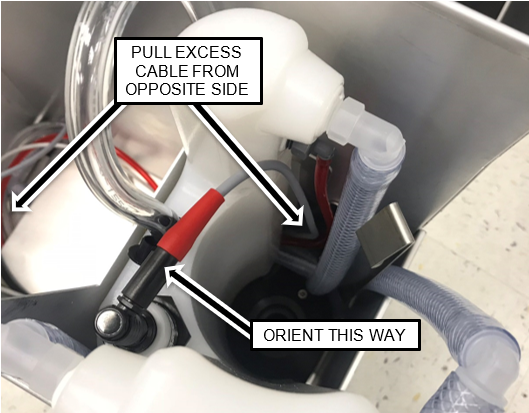
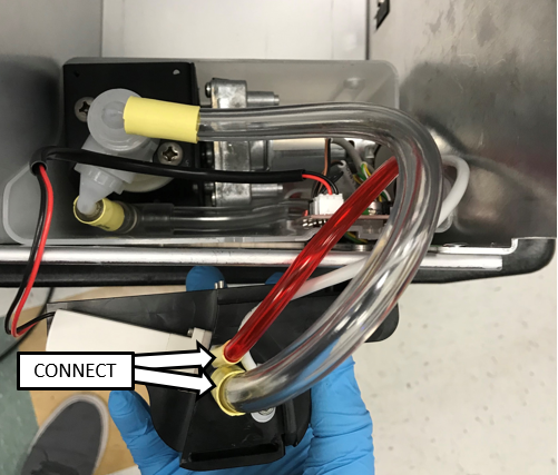
      Note—The 1/4" flexible tubing should form a u-bend above the "tower" of the vacuum bottle as shown but not above the top of the drawer. The tubing lengths can be adjusted by pulling the tubing from left side of the drawer or vice versa.

    6. ClosedAlign the key features and connect the right-angle connector of the Float Sensor to the Float Assembly connector.

    7. ClosedOrient the connector as shown below, and pull any excess cable from the other side of the drawer.

    8. Closed
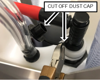
Cut off and discard the dust float assembly dust cap.

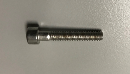
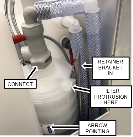
    9. Apply vacuum grease to the O-rings on each end of the GAC vacuum filter.
    10. ClosedInstall the Odorcarb Vacuum Filter with the Flow Arrow pointing UP into the Filter Block as shown below.
      Note—The protrusion on the filter should be oriented to the right.
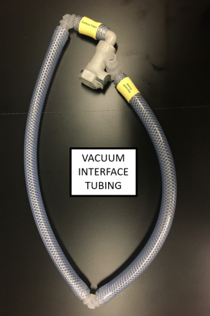
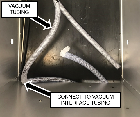
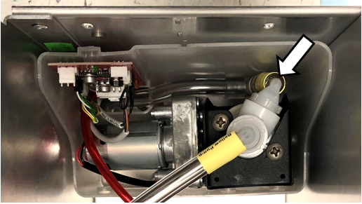
      The retainer bracket will be above the top surface of the filter when the filter is fully seated.

    11. Connect the Quick-connect on the Vacuum Interface tubing to the top of the Vacuum Filter.
  6. ClosedInstalling the Bellows Pump and Removable Waste Bottle Coupling Block
    1. ClosedRemove and retain the three mounting screws securing the Guide Plate to the Pump Housing.
      Use a 3 mm Allen key.

    2. ClosedDisconnect the Flood Sensor and remove the Guide Plate from the housing.

    3. ClosedDisconnect and remove the Transfer Pump from the pump housing.

    4. Remove the transfer pump from the housing.
    5. Position the housing in the front left of the drawer and route the cables and tubing through the opening in the housing as shown.
    6. ClosedConnect the CAN cable to the PCBA and tuck the excess CAN cable under the shelf so the housing can be moved into position.

    7. ClosedConnect the Full/Empty Sensors, the Waste Bag Sensor, and the Float Sensor Cables to the PCBA as shown.
      Note—Make neat service loops with the excess cable.

    8. ClosedRemove and discard the protective end caps from both barbed fittings on the Transfer Pump.
      Orient the fittings as shown.
      Note—It may be necessary to slightly loosen the coupling nuts to adjust the positions of the fittings.
      Hand tighten the coupling nuts (DO NOT OVER TIGHTEN).
      Apply vacuum grease to the exterior surfaces of both barbed fittings.

    9. ClosedConnect the 1/4" flexible tubing to the barbed fitting on the side of the pump that is facing downward, while placing the pump into the housing as shown.
      Note—The routing of the tubing should form a S-shaped bend as shown below.
    10. ClosedConnect the short piece of 1/4" flexible tubing to the top barbed fitting on the Transfer Pump.

    11. Position the Removable Waste Bottle Coupling Block above the pump assembly and connect the Solenoid Valve and Bottle Presence Sensor Cables to the PCBA.
    12. ClosedApply vacuum grease to the external surfaces of the two barbed fittings under the Removable Waste Bottle Coupling Block.

    13. ClosedConnect the 1/4" and 1/8" flexible tubing to their respective barbed fittings on the coupling block as shown.

    14. ClosedPlug in the Pump Motor Cable into the PCBA and route the flexible tubing in a "d" shape as shown.
      Note—
      Pay close attention the tubing at the both barb fittings.
      Ensure there are NO kinks in the tubing.
      Ensure there is NO stress on the barb fittings.

    15. ClosedConnect the Flood Sensor Cable (located on the guide plate) to the PCBA as shown.

    16. ClosedPosition the Guide Plate in the Pump Housing as shown.
      Note—The Guide Plate should be to the left side (inside) the metal chassis around the bellows of the Transfer Pump as shown.

    17. ClosedPosition the Coupling Block such that the Guide Plate tab is inserted into the slot on the underside of the Block and the Block Guide Pins are in the slots in the left side of the drawer.
      Note—Tubing color will be clear.

    18. ClosedSecure the Coupling Block in position using the screws and washers supplied in the kit
      (or retained from the original block).

    19. ClosedSecure the Guide Plate in the housing with the 3 screws removed in a previous step using a 4 mm Allen key.

  7. ClosedFinish Installation
    1. ClosedApply vacuum grease to the O-rings on BOTH of the New Removable Bottles.

    2. ClosedInstall one of the Waste Bottles.

    3. ClosedAdjust the height of the Coupling Block such that the weight of the Waste Bottle rests on the shelf and not the Coupling Block. Loosen and re-tighten the Coupling Block mounting screws to make necessary adjustments.
      Note—There should be a small gap between the two parts of the connection.

    4. Reinstall the Waste Drawer on the drawer rails.
    5. Reinstall the Waste Drawer Front Cover.
  8. Continue to Universal Fluids on the Fly Module Installation