LWOTF, New Complete Waste Drawer Installation

Parts and Materials Required

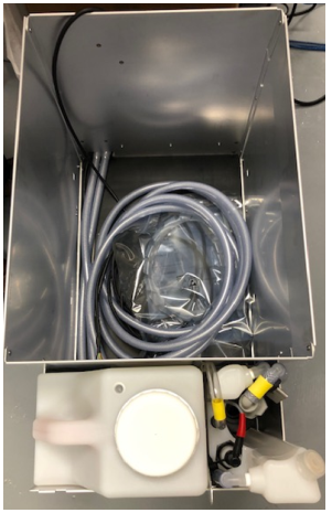
  • Vacuum Tubing (if System has been in Service for 1yr or more)

Procedure

  1. Remove and prep the Waste Drawer Cover (Steps 2 - 5).
    If Waste Drawer Cover has already been prepared, skip to Step 6.
  2. ClosedSlide the Waste Drawer open as far as possible.
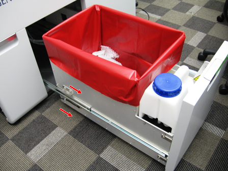
  3. Safely remove and discard the solid waste.
  4. Remove the Waste Bottle, discard the liquid waste and set the bottle aside.
  5. ClosedRemove the Waste Drawer Cover and set aside
    1. ClosedRemove the 4 screws from the Waste Drawer.
    2. ClosedRemove the screw that secures the Waste Drawer front cover panel to the bracket.
    3. ClosedRemove the front cover panel from the Waste Drawer.
    4. Closed!!! IMPORTANT!!!
      Replace the bracket mounting screws with button head style screws and set the cover aside as needed.

  6. Closed
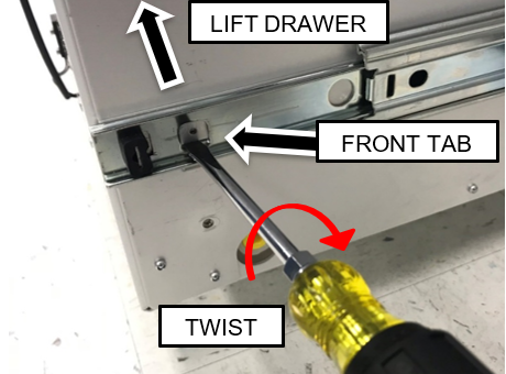
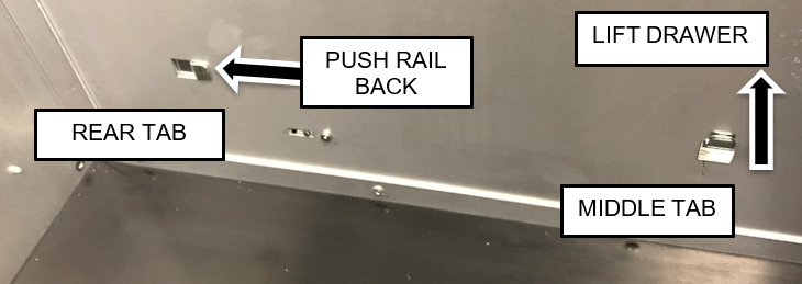
Remove the Waste Drawer from each of the drawer rails and move in front of the UFD or out of the way.
    1. Pull the drawer up to free it from the forward two tabs.
      Note—To assist in lifting the front of the drawer off the front tab, insert a flat blade screwdriver below the lower edge of the tab and twist while pulling up on the drawer as shown below.

    2. Slide the drawer rail back to free if from the rear tab

  7. Closed
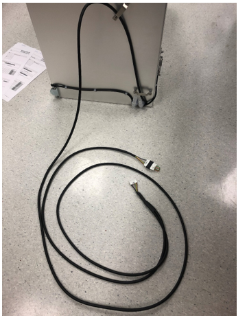
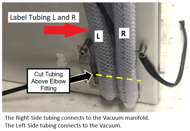
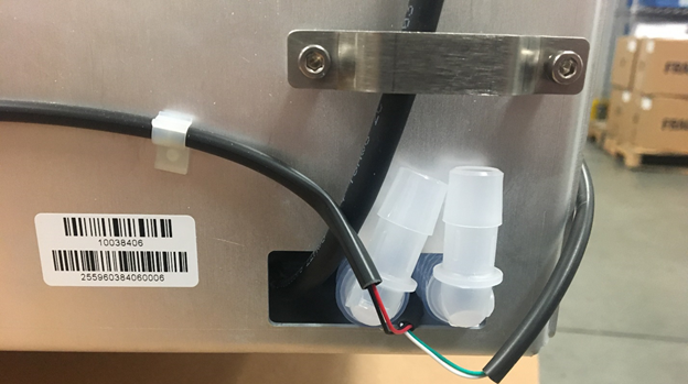
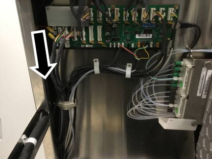
Label the tubing L and R (as shown below) and cut the vacuum tubing just above the elbow fitting.

    Note— If the system has been in service for 1 year or more, replace the vacuum tubing from the back of the waste drawer to the vacuum and manifold.

    If reusing the tubing from the back of the drawer to the vacuum and manifold, be careful not to cut too much tubing to ensure the drawer closes properly.

    The Right Side tubing connects to the Vacuum manifold.
    The Left Side tubing connects to the Vacuum.

    Note—For Panther System #1937 and below, complete the following.
    ClosedInstall the magnet plate from the existing drawer onto the drawer provided.


    ClosedRemove the magnetic plate from the new drawer.

  8. Closed
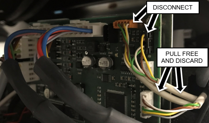
Disconnect the waste bag and bottle sensors from the Cooling Module PCB.
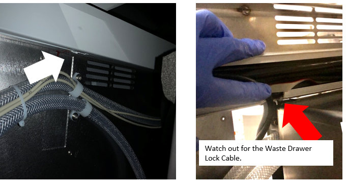
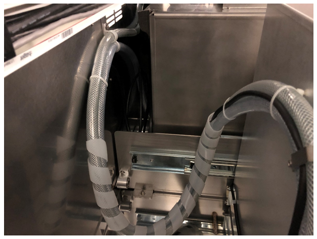
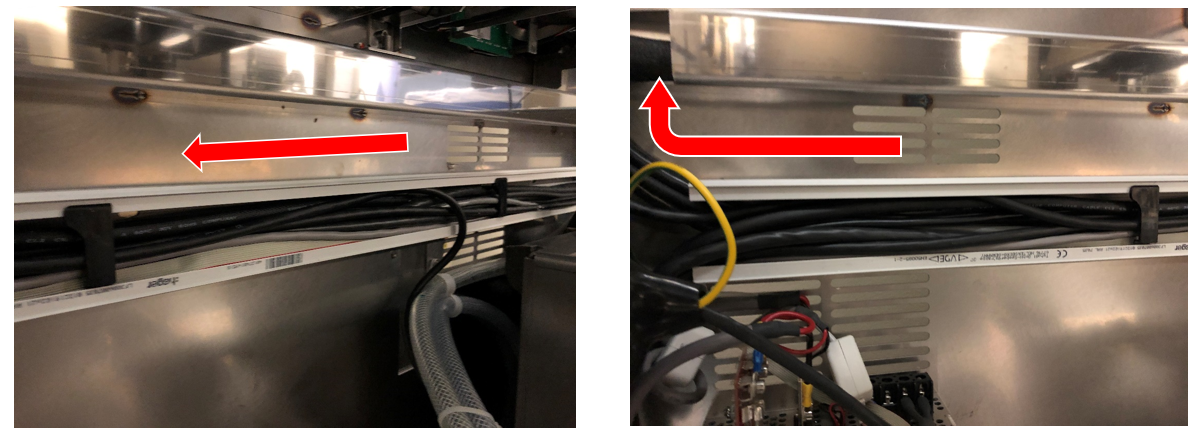
    Pull cables from behind Vacuum and Cooling Module.
    Note—For easier access open the Universal Fluids Drawer, unlatch the Vacuum Module and slide it forward to allow the cables to be pulled free.

  9. Remove the horizontal Cable Chase Cover.
  10. ClosedNotch the bottom of the Chase approximately 1” to the left of the existing cable clamps.
     

    Note— Some Chase have "flaps" that the cover rides on that can be easily removed - if so no need to cut a notch.


    Note—

    When cutting a notch in the bottom of the conduit, be careful not to cut any wires in the conduit.

    Specifically watch out for the Waste Drawer Lock Cable.
    The Waste Drawer Lock Cable is easy to miss as it usually sits at the bottom and is the same color as the chase.


    Use a zip tie to gather all the cables and move them out of the way, before cutting the notch.

  11. Closed
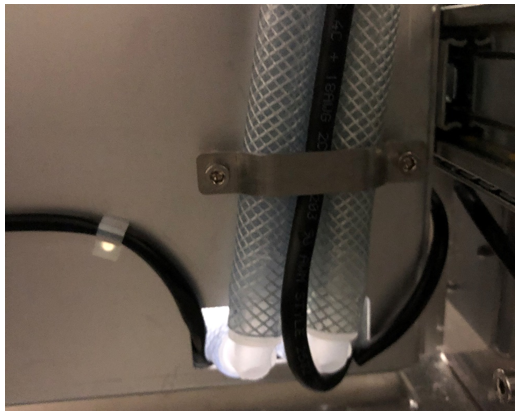
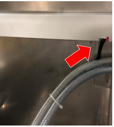
Connect the vacuum tubing to the appropriate fitting (L- vacuum pump / R – vacuum manifold).

  12. Closed
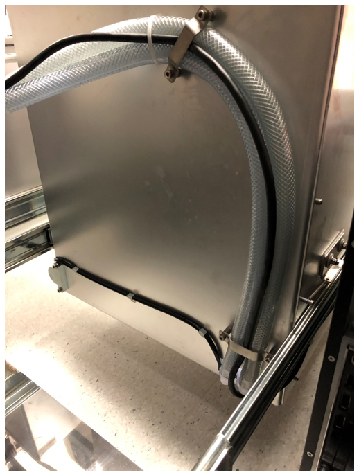
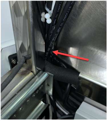
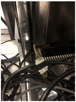
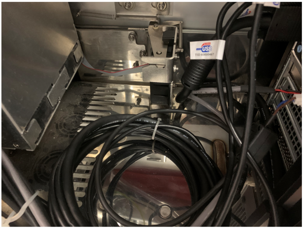
Route the new drawer's CAN cable
    1. Route the CAN cable between the vacuum tubing of the lower clamp.

    2. Route the CAN cable between the tubing of the upper clamp.

    3. Route the CAN cable along the Vacuum tubing.
      Note—Cut and discard existing zip ties where necessary and replace with new zip ties. For systems with the spiral cable wrap, complete the cable replacement on the front half first before replacing the cables in the rear half.
      Note—If installing the Waste to Drain Module this would be a good time to begin that installation so the drain tube and signal cable can be routed with the CAN BUS cable.

      Caution—Be careful to maintain the original positions of the tubing.
    4. Route the CAN cable up through the notch in bottom of chase to the left and up behind the cooling lines towards the Main COP.

  13. ClosedReplace the Cable Chase Cover.

  14. Closed
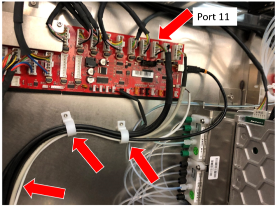
Route and Connect the CAN cable to the COP. 
    Note— If upgrading a Panther Fusion, the Waste Drawer CAN cable will plug into Port 11 on the COP board and the Fusion Sidecar CAN cable will plug into Port 12. If a jumper is present, it may be discarded.
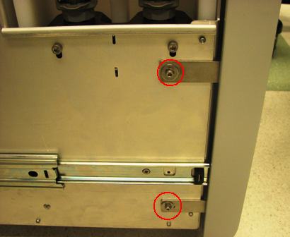
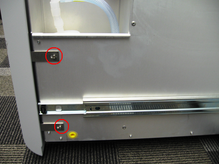
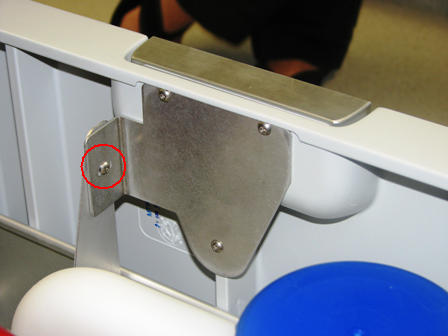
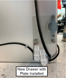
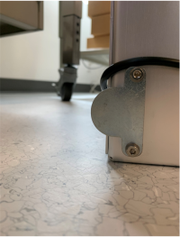
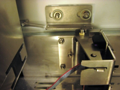
    Note— Systems 01936 and below will require relocating the magnetic latches when the waste drawer is installed
    1. Closed Connect the Origin to the next open port on the Main COP. The next open port in most systems will be Port 11.
      If a jumper is installed in Port 11, move the jumper to Port 12 and install the Origin in Port 11.
      Note—Open the Service Drawer for easier access.

    2. If this Panther is connected to a Track, route the short branch of the CAN cable to the Shuttle.
    3. ClosedIf the Panther will NOT be connected to a Track, route the short branch of CAN Cable inside the left side of the system frame.
      Ensure that the mid-bay drawer will not pinch any cables when closed.
      Note— Both branches of the CAN cable may NOT be able to be clamped. If these cables cannot be clamped together, then route the short branch to the left of the clamp and tie-wrap as needed.

  15. Install the Waste Drawer onto its rails and re-install waste drawer cover
  16. Closed
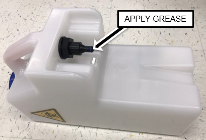
Apply High Vacuum Grease to the O-rings on ALL of the New Removable Bottles.

  17. Install one of the Removable Bottles in the Waste Drawer.
  18. ClosedClose the Waste Drawer and verify that it closes with minimal force.
    Adjust tubing and cable alignment (at the rear of the drawer) as needed.
    1. ClosedVerify any computer cables will not interfere with the Drawer lock.

    2. ClosedEnsure lock pin is aligned with Drawer lock.

Note— Instrument set-up can be run at this point.

Continue to Universal Fluids on the Fly Module Installation