Parts and Materials Required
- 7 mm nut driver
- Heat sink compound
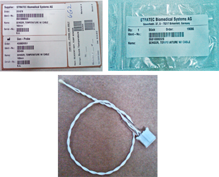
 SAMPLE/REAGENT BAY, TEMP SENSOR
Time Required
- 30 minutes
Removal Procedure
- Put on proper PPE.
- Remove the Reagent Bay.

Wear clean nitrile gloves while performing the following procedures. - Place the module upside down on a prepared work surface.
- Using a 7 mm nut driver, remove the four nuts that secure the foam bottom to the module and remove the foam.
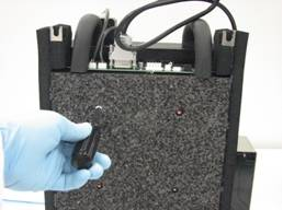
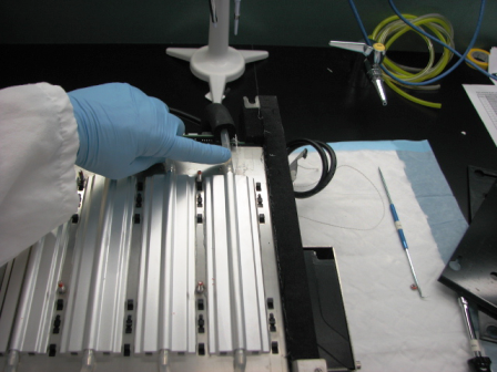
- Locate and remove the thermistor from the cooling bay.
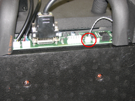
- Disconnect the thermistor connector from the main PCB.
Replacement Procedure
|
|
Caution—Be careful not to damage the delicate wires when replacing the thermistor. |
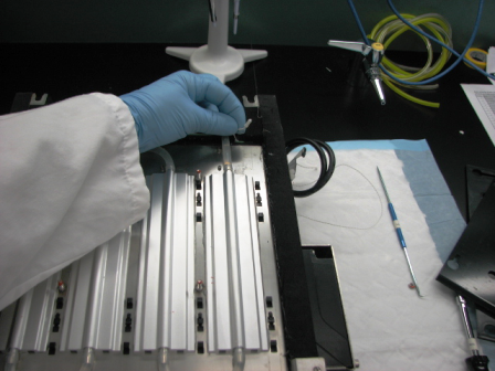
- Install the thermistor and plastic guide into the module cooling plate. Assure that there is sufficient heat sink compound to fully coat the thermistor when inserted into the cooling plate.
- Connect the thermistor to the main PCB.
- Reinstall the foam on the underside of the module. Do not over tighten the nuts that retain the foam as they could easily cut through the foam.
- Install the Reagent Bay.
Alignment/Calibration
Verification
- Start up Service Software.
- Using Service Software, verify that the Reagent Bay temperature is within acceptable range.
- Using Service Software, open and close the shutter and visually confirm that it operates properly.
- Scan racks with reagent bottles in all four lanes.
- Verify the detection of rack presence.
 button at the top of the page to send feedback, comments, or change requests.