Parts and Materials Required
- Hex wrench, 3 mm
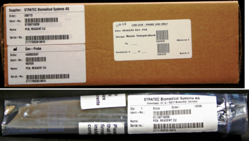
 REAGENT BAY, PCB
Time Required
- 30 minutes
Removal Procedure
- Put on proper PPE.
- Remove the Reagent Bay.

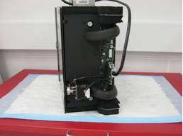
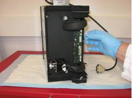
Wear clean nitrile gloves while performing the following procedures. - Place the module on a properly prepared surface in an orientation that is comfortable to work on.
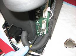
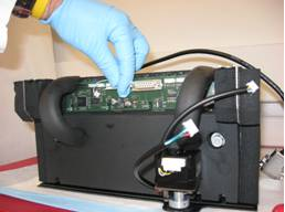
- Remove the connectors for the barcode scanner, thermistor, and motor.
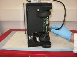
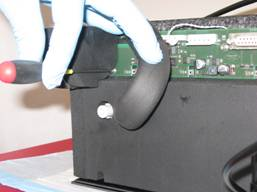
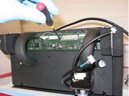
- Using a 3 mm hex wrench, remove the three 4 mm screws that secure the PCB. Two of these screws are located behind the foam, which needs to be displaced in order to access them.
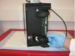
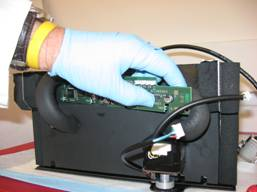
- The PCB can be removed without disconnecting the liquid cooling interconnect hoses by sliding the board to one side of the module and squeezing it past the opposite hose.
Replacement Procedure
- Reverse the removal procedure.
Alignment/Calibration
- Run Instrument Setup to install firmware to the module.
- Auto-teach the Reagent Pipettor to the Reagent Bay.
Verification
- Start up Service Software.
- Using Service Software, verify that the Reagent Bay temperature is within acceptable range.
- Using Service Software, open and close the shutter and visually confirm that it operates properly.
- Scan racks with reagent bottles in all four lanes.
- Verify the detection of rack presence.
 button at the top of the page to send feedback, comments, or change requests.