Parts and Materials Required
- Proper PPE
- Absorbent pad
- CABLE, LUMINOMETER, PMT, FERRITE
Time Required
- 10 minutes (Removal and Replacement of the new PMT
 Photomultiplier tube cable)
 - 10 minutes (Luminometer Darkcount Procedure)
- 40 minutes (OQ Procedures)
Preparation
- Put on proper PPE.
- Open the right side panel door of the Panther System.
- Open the Service Drawer.
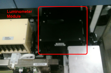
- Locate the Luminometer module.
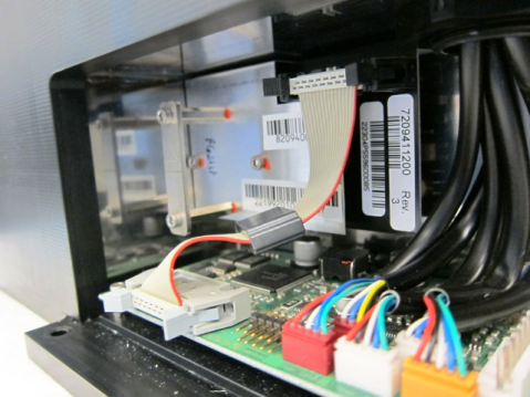
Removal Procedure
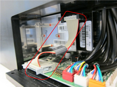
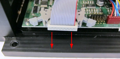
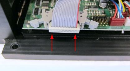
- Locate the PMT Cable and connections.
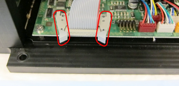
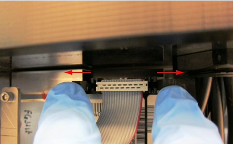
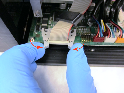
- Carefully release the two retaining latches that secure the PMT cable to the main Luminometer PCB by pushing the latches in an outward direction.
- Gently disconnect the PMT cable from the main Luminometer PCB.
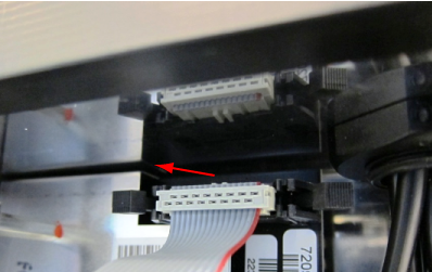
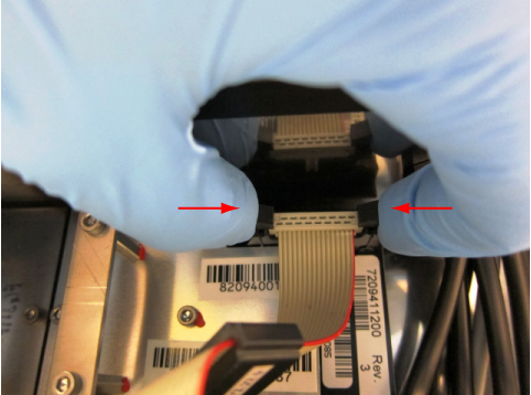
- Disconnect the PMT cable from the PMT PCB using the same method described in steps 2 and 3.
Replacement Procedure
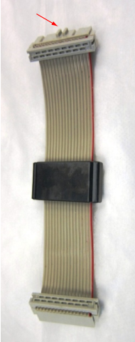
- Obtain a new PMT cable with the ferrite EMI filter. The end of the cable that attaches to the PMT PCB is the connector with the key feature oriented away from the ribbon cable.
- Securely connect the new PMT cable to the main Luminometer PCB by pushing the PMT connector into the mating PCB connector and squeezing the two retaining latches inward. Make sure the latches are fully snapped into place—the connector must be fully seated.
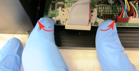
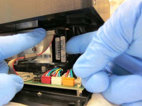
- Support the back of the PMT PCB as shown below and press the PMT cable connector into the mating PMT PCB connector.
- Squeeze the two retaining latches inward. Make sure the latches are fully snapped into place—the connector must be fully seated.
- Verify all connectors are secure and the cable is not interfering with any other components.
- Securely close the Service Drawer.
- Close the right side panel door of the Panther System.
Alignment/Calibration
- None
 button at the top of the page to send feedback, comments, or change requests.
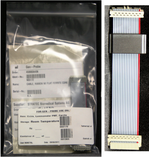