Parts and Materials Required
- Hex screwdriver, 2.5 mm long
- LOAD STATION, MAIN PCB
Time Required
- 30 minutes
Removal Procedure
|
|
Wear clean nitrile gloves while performing the following procedures. |
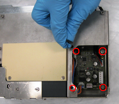
- Put on proper PPE.
- Remove the HPA Load Station module.
 Using a 2.5 mm hex wrench, remove the four screws on the corners of the PCB.
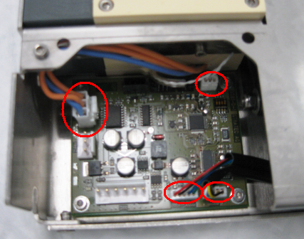
- Remove the PCB from the module.
Replacement Procedure
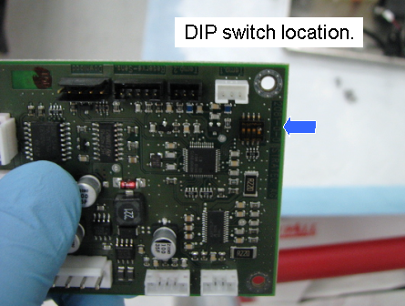
- Be sure that the DIP switches on the new board are set correctly.
- Reverse the removal procedure.
- Reinstall the HPA Load Station module onto the system.
- Run the Panther Instrument Setup (Firmware) procedure.
Alignment/Calibration
- Using Service Software, teach the Distributor to the HPA Load Station.
- Teach the Pipettor to the HPA Load Station.
 button at the top of the page to send feedback, comments, or change requests.