Parts and Materials Required
- Ball driver or Allen key, 2.5 mm
- 5.5 mm hex driver or wrench
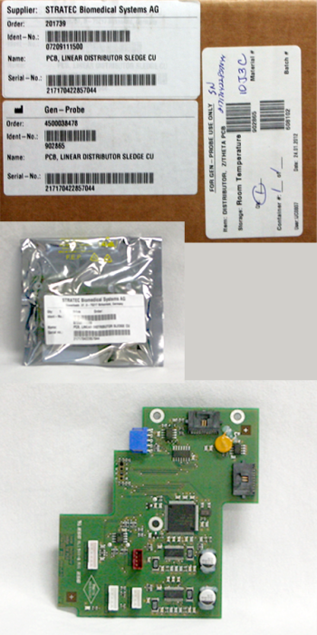
 DISTRIBUTOR, Z/THETA PCB
Time Required
- 30 minutes
Removal Procedure
- Put on proper PPE.
- Launch Panther FSE Shield software.
- Install Panther System firmware to the module.
- Run the Panther System Firmware Installation script to save the teach parameters so they do not have to be taught again after the PCB is replaced.
- Shutdown the Panther System and PC.
- Remove the Luminometer Injector.
- Carefully open the Service Drawer.
- Manually move the Distributor head into position next to the Service Queue.

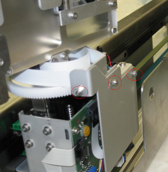
Note—The Transition Incubator can be removed for extra space to access the Distributor Theta Board. - Using a 5.5 mm hex driver, unscrew the two nuts securing the Z/Theta PCB cover, and set it aside.
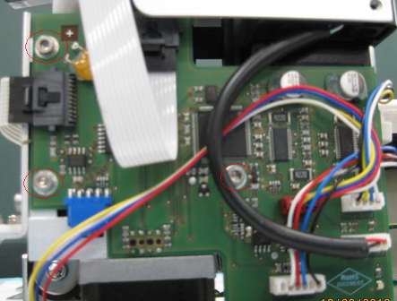
- Unplug all cables from the Z/Theta-axis PCB.
- Using a 2.5 mm ball driver or Allen key, unscrew the three bolts and remove the Z/Theta-axis PCB.
Replacement Procedure
- Insert the new Z/Theta PCB and fasten by screwing in three bolts.
- Plug in all cables to the Z/Theta-axis PCB, note that the correct location for each cable is written on the PCB.
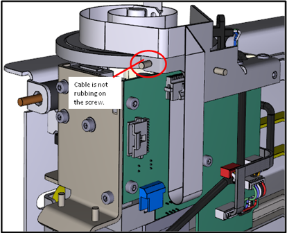
- Refasten the Z/Theta PCB cover. The placement of the theta flex cable is important. Refer to the following picture. Make sure the fold is not sandwiched behind the cover.
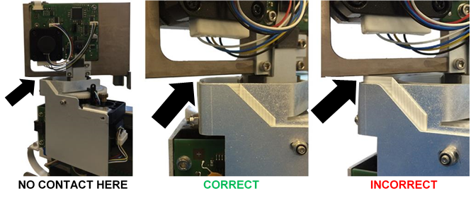
- Confirm that all wires are tucked behind the PCB cover, and will not get snagged during normal movement.
- Close the Service Drawer.
- Reinstall the Luminometer Injector.
- Install Panther System firmware to the module.
Note—If Firmware Installation script was not run prior to replacement of the PCB, then auto-teach the distributor to all locations, starting with the Input Queue. - Start up Service Software.
 button at the top of the page to send feedback, comments, or change requests.