Panther Chassis Modification to Track Ready
These instructions apply to all Panther Systems with serial numbers below 01938.
This procedure requires 2 people to complete the modification.
Parts and Materials Required
- Panther Tool Kit
- Leather or Cut Resistant Work Gloves
- Drill Motor (Source Locally)
- Jig Saw with Sheet Metal Blade (Source Locally)
- Extension Cord (As needed)
- Absorbent Pads
- Tape, Magnets, or similar
- Panther Track Ready Upgrade Kit
- Track Ready Bracket, Vacuum Manifold
- Track Ready Shuttle Mounting Bracket
- Screw, SHC, M4x8, 18-8 SS
- Screw, SHC, M5x10, 18-8SS, 0.8 mm Pitch
- Screw, SHC, M5x8, 18-8 SS, 0.8mm Pitch
- T-Nut
- Assembly, Panther Track Ready Templates Kit
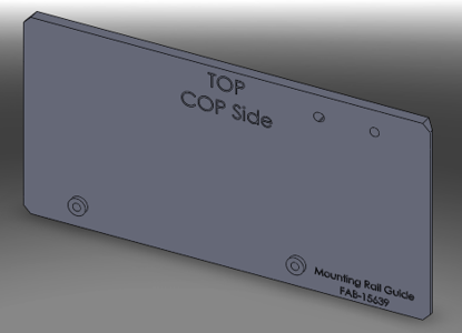
 Mounting Rail Guide, COP Side
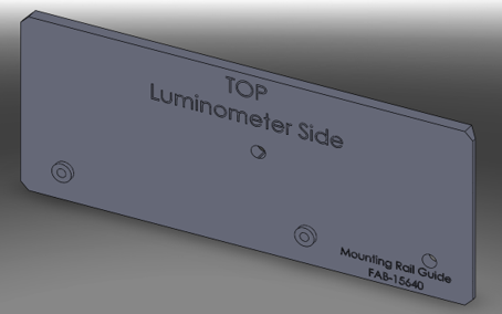
- Mounting Rail Guide, Lumo Side
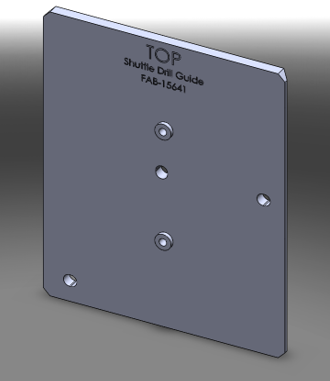
- Shuttle Drill Guide
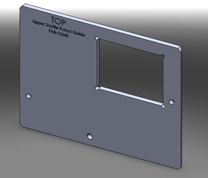
- Template, Upper Shuttle Cutout
- Template, Lower Shuttle Cutout
- Panther Trax Punch Kit
- Greenlee Punch Kit B (Punch and Ram)
- Greenlee Type 3" X 4" Punch (Custom)
- Greenlee 1 1/4" Punch
- Greenlee draw stud for 1 1/4" punch
- Greenlee 3/4" Nut for Draw Stud (extra)
- Step Drill (1/8" to 1/2")
- Split ring stop collar set
- 5.5 mm short length Drill Bit
- Amana Tool Universal Drill Depth Stop
- File for stainless steel
- File handle
- Cut Resistant Gloves
- AFA Deburring Tool with 10 Blades
Time Required
- 3 Hours
Procedure
Part A: Punching Holes for Track Access
- Put on proper PPE.
- Power down the Panther System and PC.
- If the Panther is attached to a Fusion module, unfuse the Panther from the Fusion Module.
- Move the Panther System so that it has 460mm (18") of minimum clearance behind the system.

Note—This temporary position will allow for easier access during this procedure. - Raise the feet of the system with an adjustable wrench so that the wheels contact the floor.
- Roll the Panther System to create your working space.
- Lower the feet to secure the Panther System in place.
- Remove the Pipettor Gantry Safety Shield if installed.
- Remove the divider between the Sample Bay and Tip Drawer.
- Manually move all Pipettors to their upper most Z-height and to the front left (above Reagent Bay) of the system.
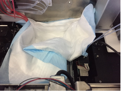
- Place absorbent pads over the Upper Bay modules to protect the inside of the system.
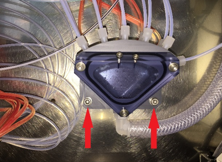
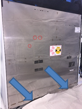
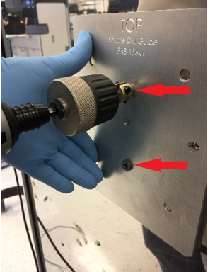
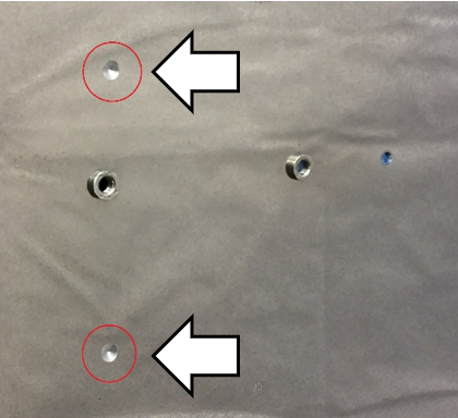
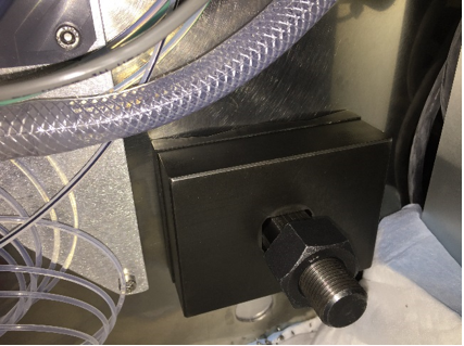
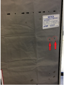
- Remove the 2 screws (see red arrows below) retaining the Vacuum Manifold to the back wall of the Panther. Save the screws for reinstallation.
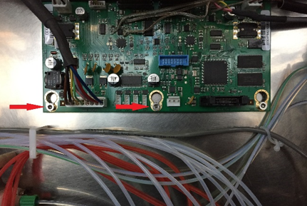
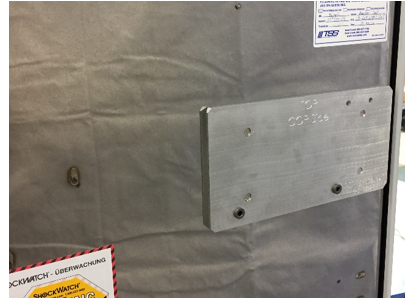
- Remove the 2 screws on the Pipettor CU PCB (see red arrows below) and install the Vacuum Manifold relocation bracket on top of the PCB using the original screws.
Note—Route all tubing and cabling in front of the new bracket. - Attach the bottom of the Vacuum Manifold Relocation Bracket with the provided screw as shown below. (The image shows the Vacuum Manifold installed on the Vacuum Manifold Relocation Bracket.)
- Install the Vacuum Manifold onto the Vacuum Manifold Relocation Bracket using the screws removed in Step 9.

Caution—Be sure that the Output Queue and Magwash Magnetic washer Aspirator lines are not kinked or tight.Note—Check that the Output Queue Aspirator reaches its upper and lower positions without stressing the aspirator lines. - (Optional) Perform either a or b. Leave the Output Queue in position (a) or remove it for convenience (b).
- Place absorbent pads above the Output Queue OR the area vacated by the Output Queue, if removed.
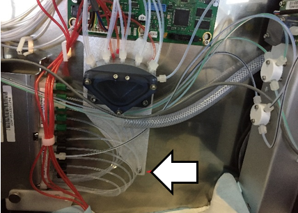
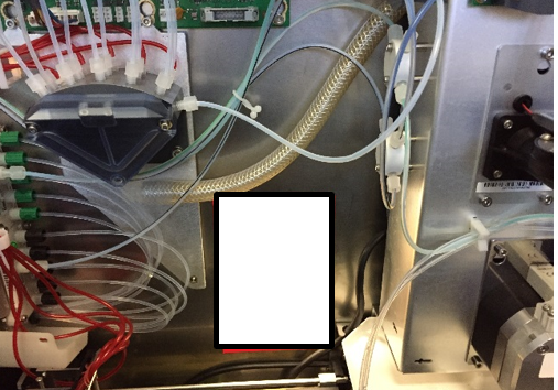
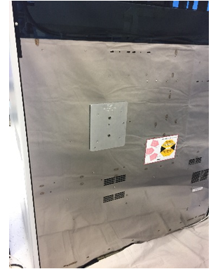
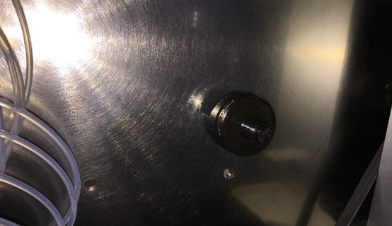
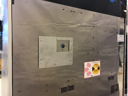
Note—Use tape or magnets to secure the absorbent pads in place. - Determine the final location for the holes that will be punched and verify that no power/communication cables or vacuum lines will be damaged during the drilling or punching process (see white rectangle below).
- Place absorbent pads on the floor behind the Panther where the holes will be punched.
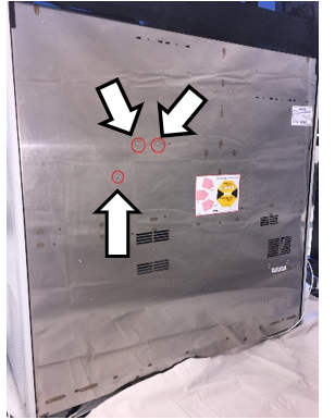
- Align the first template, Shuttle Drill Guide to the 3 PEM nuts on the back panel of the Panther System as shown below. The guide is held in position by embedded magnets.
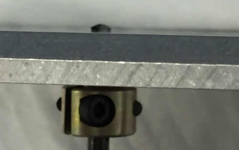
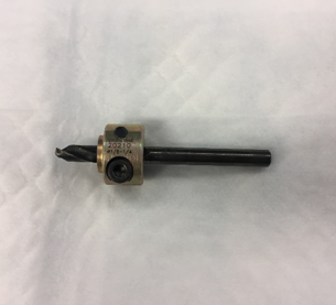
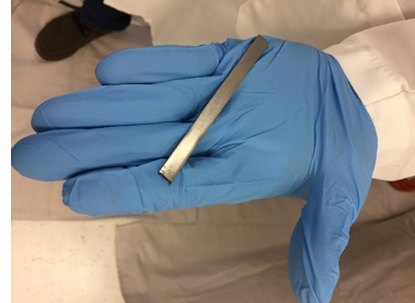
- On a 5.5mm drill bit, set the stop collar as shown to limit depth of penetration.
- Use the 5.5mm drill bit fitted with the stop collar on low speed to drill a dimple in each guide hole of the template.
Caution—Hold the template in place while drilling to prevent it from wobbling or moving off the back of the system. - Remove the template.
- Finish drilling the two 5.5mm holes. Be sure the drill stop collar is in place.
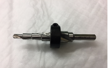
- Set the stop collar to drill a 3/8" hole.
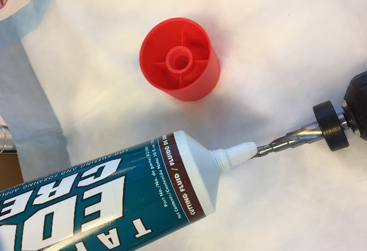
- Apply a layer of lubricant to the step drill bit.
- Enlarge the existing holes to 3/8" using a drill on low speed.
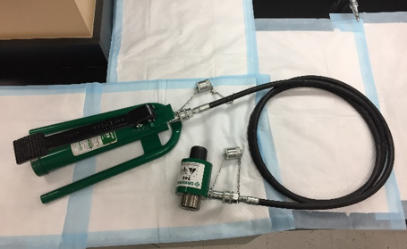
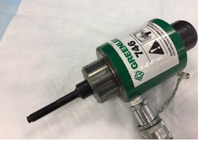
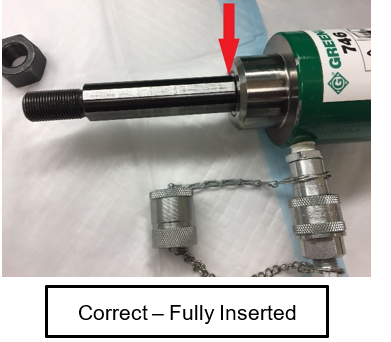
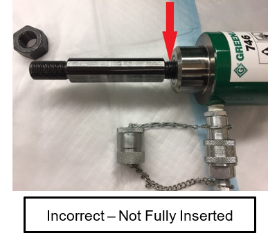
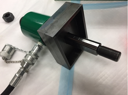
Note—Be sure that the drill is perpendicular to the surface being drilled so the drill does not drift. - Set up the hydraulic pump and ram according to their separate instructions. The final assembly is shown below.
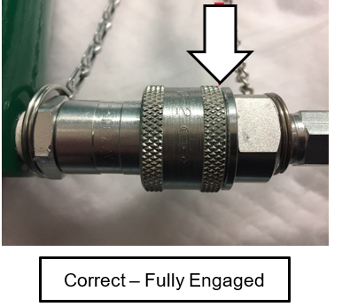
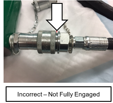
Caution—Review the safety warnings in the Greenlee instruction manuals for the hydraulic pump and ram. The pressures reached create dangerous conditions that should be known by everyone working with the equipment. - Screw the hose attachment collar onto the pump and ram (see image).
- Press the pressure release lever on the hydraulic pump (see image) to check that the ram is fully extended.
- Insert the small 3/8” X 3/4” draw stud adapter into the hydraulic ram (see image).
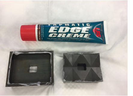
- Lightly lubricate the punch and die (see image).
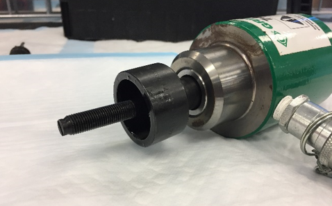
- Slide the small 1 1/4” punch die onto the draw stud with the open end of the die facing away from the ram (see image).
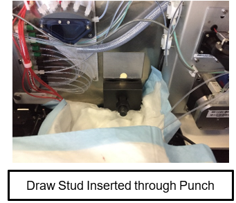
- Insert the draw stud through one of the 3/8” holes just drilled in the back of the Panther.
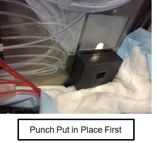
- Thread the punch of the punch/die onto the draw stud from inside the Panther with the cutting surface facing the material (see image from inside the Panther System). Thread the punch all the way down the draw stud, finger tight, to reduce the distance the ram needs to pull.
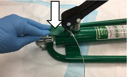
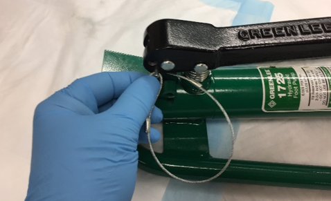
- Remove the pump hold-down pin from the pump handle (see image).
Caution—Wear safety glasses during any punching process. The hydraulic ram exerts pressures in excess of 150,000 kPa (22,000 psi) during its punch cycle - Remind all personnel present to not stand directly behind the ram while it is being cycled. There are dangerous pressures present and a system failure at pressure is dangerous.
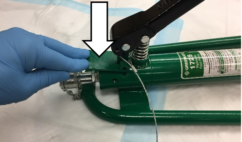
Warning—Standing directly behind the ram is extremely dangerous - With your foot, slowly and gently press the foot pump down to draw the punch against the back of the Panther.
Note—Double-check that the punch and die are in the proper locations, and no cables or hoses are pinched or cut. - Reposition the punch, as needed. If necessary, release pressure on the pump by quickly depressing the pressure release lever.
- When the hole is punched, the ram, die, and punch may fall out of the hole. Hold the ram so that the assembly doesn’t fall to the floor.
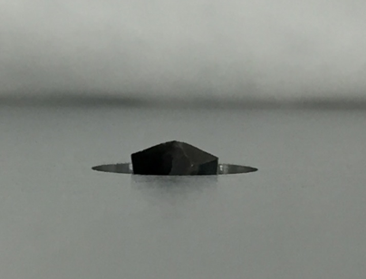
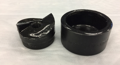
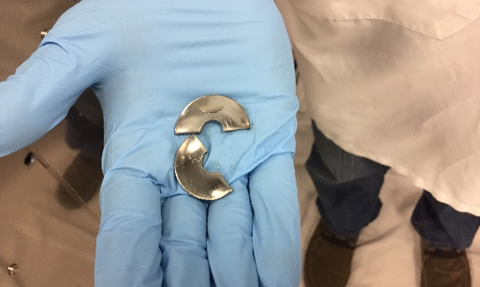
- If done properly, the resulting 1 1/4” slug left inside the punch/die is cut in half and easily removed (see image).
- Press and hold the pressure release lever on the pump while watching the ram/draw-stud fully extend.
- Remove the punch and slug from the die. Repeat Steps 31–39 in the other 3/8” hole drilled in the back of the Panther System.
- Remove the punch/die and the draw stud from the hydraulic ram.
- Insert the large 3/4” draw stud into the hydraulic ram. Screw the longer threaded portion into the ram, leaving the shorter threaded portion sticking out (see image).
- Lightly lubricate the punch and die (see images).
- Install the die portion of the large 3” X 4” punch set onto the draw stud with the open end of the die facing away from the ram. (see image).
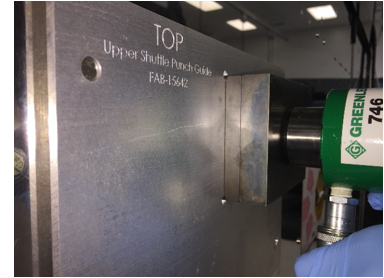
- Place the second template, Upper Shuttle Punch Guide, onto the rear of the Panther using the PEM nuts as guides (see image).
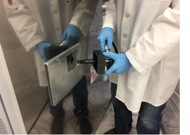
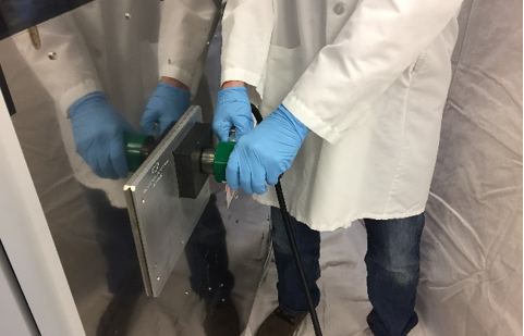
Note—Be sure the template is fully seated onto the rear of the system. One of the holes punched in the previous procedure is centered in the template cut-out. - Use an assistant during the following steps.
- Insert the draw stud through the top hole on the back of the system so the die portion fits into the guide and sits flat onto the back of the Panther (see images).
- The assistant should slide the punch portion of the punch/die onto the draw stud from inside the Panther with the cutting surface facing the material (see image). Avoid power cables and hoses so that none are damaged during the punching process.
- Screw the backing nut onto the draw stud until finger tight (see image above).
Note—The draw stud and nut are pulled into the instrument wall during the punching process. Caution—Review the safety warnings in the Greenlee instruction manuals for the hydraulic pump and ram. The working pressures create dangerous conditions that must be communicated to everyone working with the equipment Warning—Wear safety glasses during any punching process. The hydraulic ram exerts pressures in excess of 150,000 kPa (22,000 psi) during its punch cycle - While holding and watching both the punch and die, slowly and gently cycle the hydraulic pump until the punch and die are snug against the sheet metal. Double-check that the punch, die, and template are in the correct positions before cutting the hole.
- While the assistant holds the hydraulic ram, pump the hydraulic pump to draw the punch through the sheet metal (see image). It may be necessary to continue pumping after it feels like the punch has completed its cycle for the punch to release from the hole.
- When the hole is punched, the ram, die, and punch may fall out of the hole. Hold the ram so that it doesn’t fall to the floor.
- Release pressure on the pump/ram by pressing the release lever of the pump.
- Remove the Upper Shuttle Punch Guide from the back of the Panther.
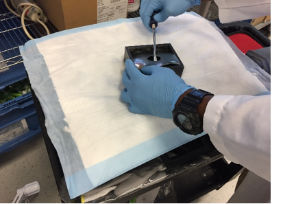
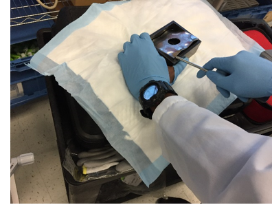
- Remove the nut, punch, and die from the draw stud. A sheet metal slug is left in the die portion of the punch/die. Carefully, remove the slug from the die using a screwdriver or similar tool. Be sure not to damage the lip of the die when removing the slug, the inside edge of the die is a cutting surface. (Optional) Wear leather or cut-resistant gloves protect your hands during removal of the slug (see images below).
- Remove any small burrs from the hole so that the next template sits flat on the back of the Panther.
- Repeat Steps 47–55 using the Lower Shuttle Punch Guide to align the punch. If the Output Queue was not removed, first, place the punch portion of the punch/die inside the Panther. Second, push the draw stud through the punch from the outside allowing the punch portion to fit behind the Output Queue actuator rails (see images). Again, take special care that the punch has not pinched any hoses or cables.
- An assistant is no longer needed.
- With an absorbent pad under the fittings, disassemble the hydraulic punch/ram and return it to its case.
Note—If another Panther system will be punched soon, leave the hydraulic punch/ram assembly connected for convenience. Leaving the assembly connected will not damage it. - Clean an spilled hydraulic oil with 70% ethanol.
- If the pump handle is still in the raised position, press and hold the pressure release lever while pressing down on the pump handle. Insert the handle retaining pin when the pump handle is positioned properly.
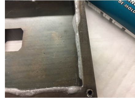
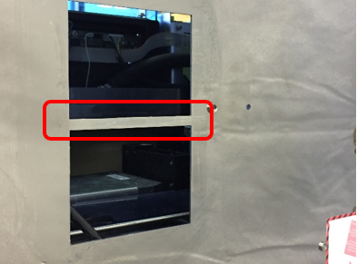
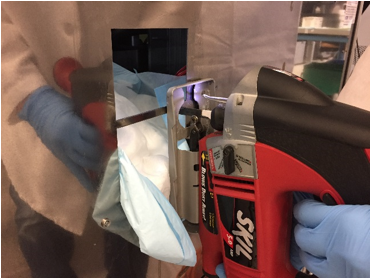
- A small web remains between the two holes (see red rectangle in image below). This web was needed during the punching process to keep the punch and die correctly positioned. Remove the web.
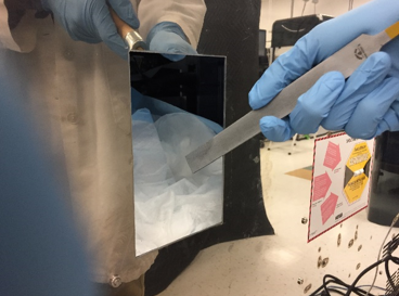
Warning—The edges of the punched hole are sharp. BE CAREFUL! - Carefully cut the web out using a jig saw with a sheet metal blade.
Note—Use slow speed for cutting the stainless steel. Cutting at high speed makes control difficult and dulls the blade.
The PEM nuts will not allow the base of the jig saw to sit flat on the back of the system. Do your best to keep the jig saw straight and square while crossing these PEM nuts.
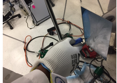
Warning—Leather or cut resistant work gloves must be worn during the deburring step. It is extremely easy to be cut by the sharp edges during this process. - Smooth the nub left by the jip saw using a file.
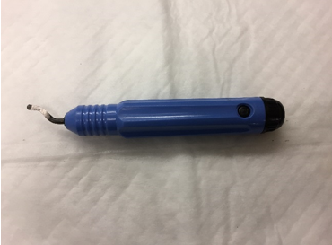
- Soften the edges of the hole using a deburring tool. De-burr all 8 edges inside and outside of the hole.
- Double-check that all sharp edges are smooth.
- Carefully remove the absorbent pads that were tapped to the inside of the Panther.
Caution—Do NOT allow any metal shavings on the absorbent pads to fall into the system. Clean up any metal shavings that remain inside. - Gather the absorbent pads that were placed behind the Panther.
Note—There will be metal shavings on the absorbent pads. Clean up any shavings remaining in the work area. - Remove any traces of cutting oil from the cutting area of the Panther System with alcohol on a lint-free wipe.
- Reconnect the Output Queue Power/CAN cable and grommet to its bracket.
- If more work will be performed inside the system (i.e. installing Trax), place fresh absorbent pads in the work area. Otherwise, restore the Panther System to its original condition and location.
Part B: Mounting Tracking Attachment Rail
- Place absorbent pads on the floor below where the following holes will be drilled.
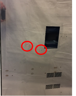
- Place the next template, Mounting Rail Guide - COP Side, on the rear of the Panther System. Align the template to the two PEM nuts (red arrows below). The template is held in position by embedded magnets.
- Open the Mid-Bay drawer during the following drilling procedure.
- Check the position of the holes to be drilled and confirm that no hoses, cables, or other parts will be damaged during the drilling of the holes.
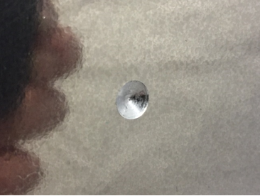
- For safety, hold the template in place while drilling. Use low speed when drilling. High drilling speeds create excess heat and dull the drill bit. Drill the two 5.5mm holes only deep enough to create a cone shaped indentation (see image). The 5.5mm drill bits should have a drill stop collar in place to reduce the possibility of damaging any hoses or cables during the drilling process.
- Remove the template and finish drilling the two 5.5mm holes. Be sure the drill stop collar is in place.
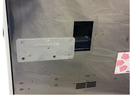
- Repeat steps 2 - 6 using the final template, Mounting Rail Guide - Luminometer Side.
Note—Refer to the red circles in the image below to identify the 2 PEM nuts to use for alignment. - Gather the absorbent pads that were placed behind the Panther System.
Note—There will be metal shavings on the absorbent pads. Clean up any shavings remaining in the work area. - Install the new Track Module and mounting rail. Proceed to Step 6 of Shuttle-to-Panther Installation.
- If the Panther System was moved and re-leveled, reteach the Linear Distributor and Pipettor.
- If removed, fuse the Fusion Module.
Verification
- Power on the Panther System and PC.
- Run an OQ using at least 2 MTUMulti-tube unit—Container used to process tests in the instrument. An MTU contains five separate reaction tubes. The MTU is moved through the instrument by the linear distributor and includes five tiplets for pipettiing to be used in the mag wash station.'s to assure the Linear Distributor is properly taught.
 button at the top of the page to send feedback, comments, or change requests.