Track Ready Shuttle-to-Panther Installation
Parts and Materials Required
- Panther Tool Kit
- Assembly, Panther Track-Ready Upgrade Kit
- ASSEMBLY, PANTHER TRACK-READY SHUTTLE INSTALLATION TOOL [ASY-12803]
- SHUTTLE INSTALLATION TOOL, BACK PLATE [FAB-15800]
- SHUTTLE INSTALLATION TOOL, LEFT SUPPORT [FAB-15801]
- SHUTTLE INSTALLATION TOOL, RIGHT SUPPORT [FAB-15802]
- SHUTTLE INSTALLATION TOOL, U CHANNEL CLAMP [FAB-15803]
- SCREW, BUTTON HEAD SOCKET, M4 X 10, 0.7 PITCH, 316SS (BAG OF 4) [SCR-01362] [McMaster-Carr P/N 94500A227]
- SCREW, THUMB, M4X8, 18-8 SS, 0.7mm Pitch [SCR-01363] [McMaster-Carr # 92558A100]
- DOWEL PIN, M4 DIA X 10MM L, 18-8 SS (BAG OF 4) [MME-03344] [McMaster-Carr P/N 91585A437]
Time Required
Procedure

|
Note— For Panther Systems with Serial Number 01939 and above proceed to Step 1. |
- Turn off the Panther System and Panther PC.
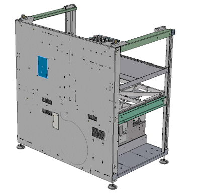
- Remove the side panels to allow access for Shuttle Installation.
- Manually move all Pipettors to their upper most Z-height and to the front left (above Reagent Bay) of the system.
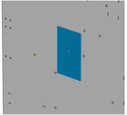
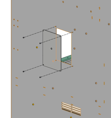
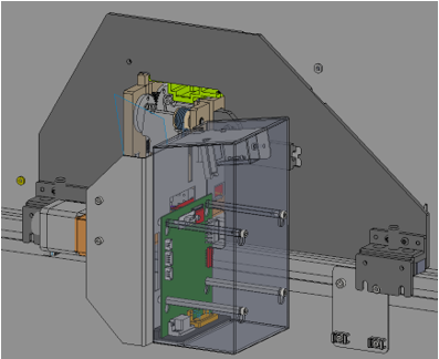
 Locate the Shuttle opening cover plate on the rear of the back panel (blue box below).
 - Remove the 4 screws securing the cover with an M2.5 hex key.
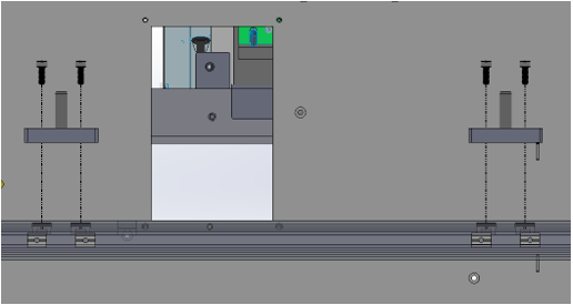
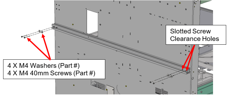
- Install the Shuttle mounting bar.
- Make sure the slotted screw clearance holes are on the correct side (see picture below)
- Remove the L-bracket that is attached to the mounting bar. Leave the T-nuts in the original location. Loosely attach the L-bracket to the bottom side of the Shuttle with two M4 nuts.
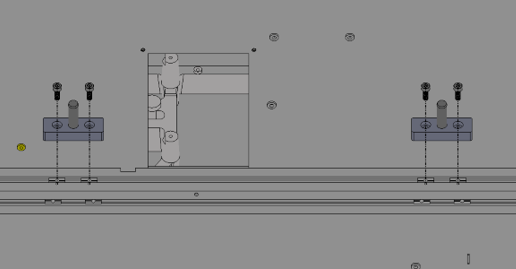
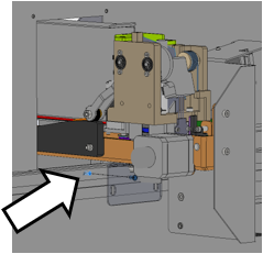
- Insert 8 T-nuts (see arrows below).
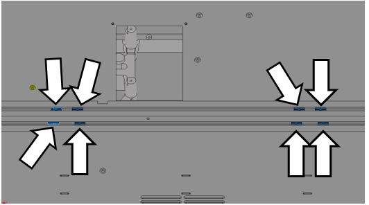
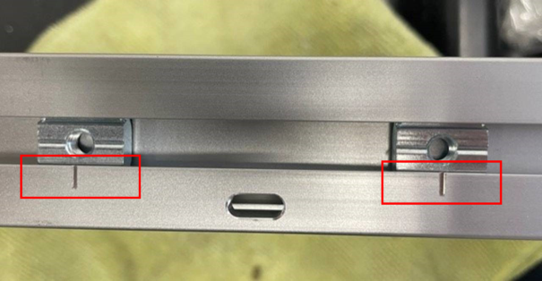
| Note—Refer to the tick marks on the mounting rail for exact location of the T-nuts. |
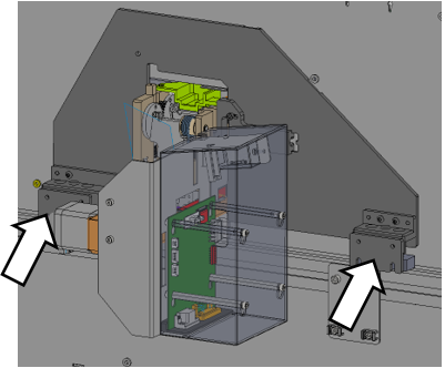
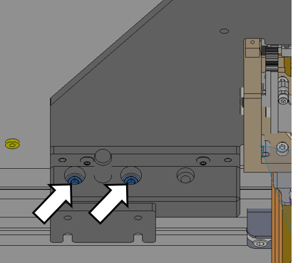
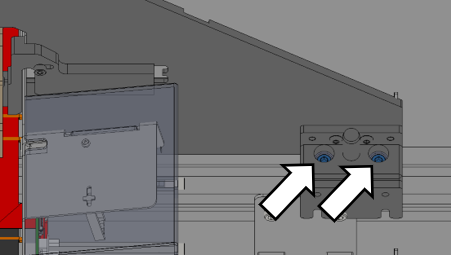
- Mount the alignment pin holders using the M5 screws and a 4 mm driver. Leave the screws loose.
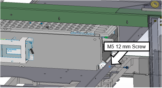
- Install one M5 12 mm screw at the Shuttle front mounting location. Leave the screw loose.
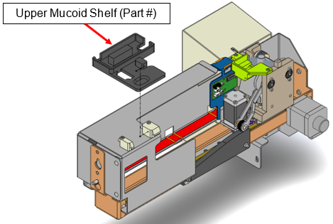
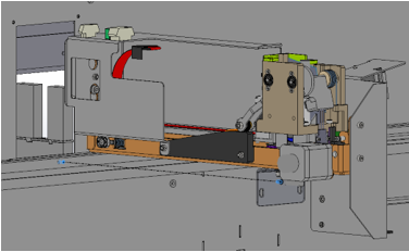
- Remove the upper mucoid shelf from the Shuttle.
- To remove the magnetic upper mucoid shelf, slide it away from the PCB and lift the shelf up. Check that the CAN cable is connected to the Shuttle PCB. Save the mucoild shelf as it will be installed after the shuttle is mounted in the Panther.
- Install the Shuttle through the back panel opening until the Shuttle locating pin enters the locating hole on the mounting bar.
- While installing the Shuttle, maneuver the front end to avoid damaging the tubing.
- Route the Shuttle CAN cable through the back panel opening while installing the Shuttle module. A channel corner cut out along the length of the Shuttle frame provides routing for the CAN cable.
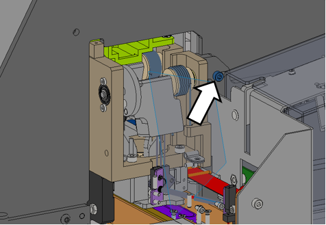
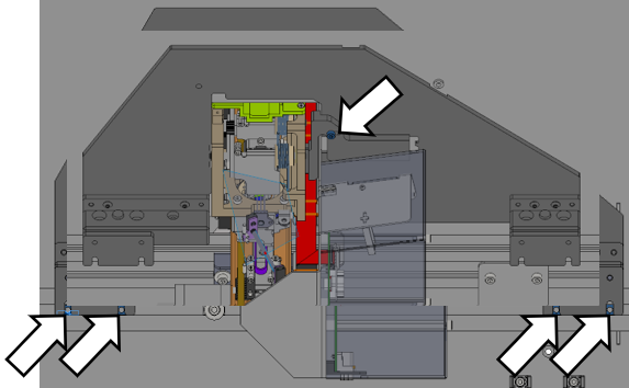
- Inside the Panther System, hang the Shuttle front end on the M4 screw through the keyhole cutout. Leave the screw loose so the Shuttle moves freely.
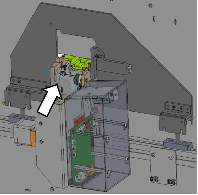
- Connect the included Shuttle CAN cable to the next free COP location from the left as shown below.
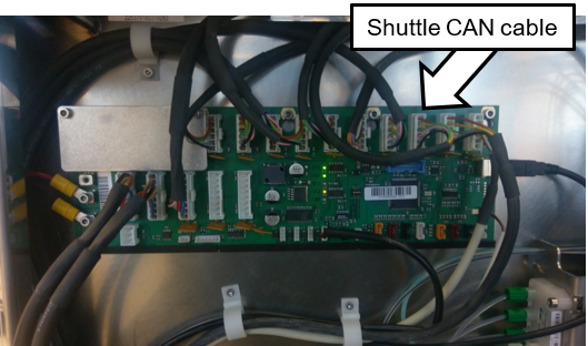
- Route the CAN cable up and over the MagWash modules.
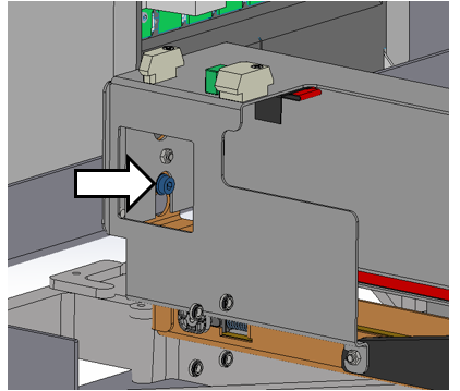
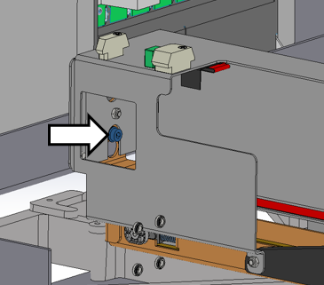
- Locate the Shuttle alignment plate on the outisde of the back panel of the Panther.
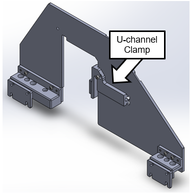
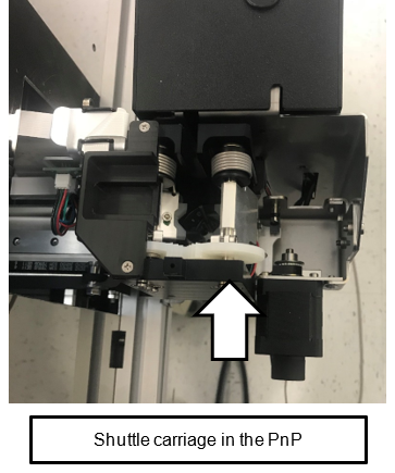
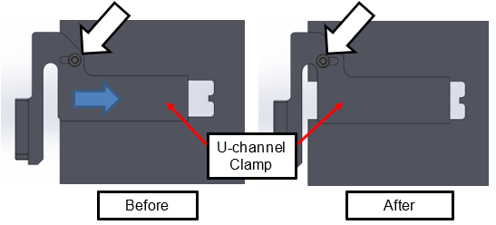
- Loosen the thumbscrew (white arrow below) and pull the U-channel clamp back. Then, retighten the thumbscrew to hold it in position.
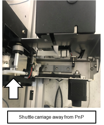
- Manually move the Shuttle carriage towards the Sample Bay and away from the Pick-and-Place (PnP) location until the alignment plate drops into the Shuttle.
- Push the Alignment Plate towards the Panther until flush with the back panel.
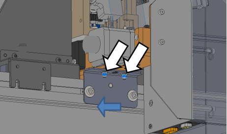
- Align the 2 Alignment Pin Holders along the mounting bar so that the pins enter the Alignment Plate.
- Lower the Alignment Plate onto the mounting bar, then push it towards the Panther until flush with the back panel.
- Loosen the thumbscrew to allow the U-channel clamp to engage.
- Slide the Alignment Plate along the mounting bar to check the U-channel is captured by the plate.
- Retighten the thumbscrew to hold plate in position.
- Inside the Panther, tighten the M4 screw at the front hanging location. Make sure the M4 screw is in the mounting keyhole and capturing the Shuttle.
- Push the L-bracket against the mounting bar and tighten the two M4 nuts using an M7 socket driver.
- Install and loosely tighten the two M4 screws to secure the Shuttle to the mounting bar.
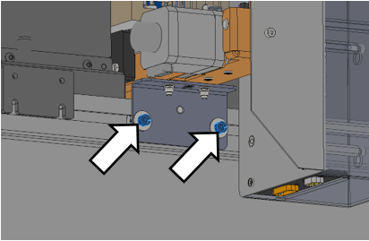
- Tighten the two M5 screws on the left side of the Shuttle to secure the Alignment Pin Holder to the mounting bar.
- Tighten the two M5 screws on the right side of the Shuttle to secure the Alignment Pin Holder to the mounting bar.
- With the open slot on the Alignment Plate, loosely locate the T-nuts for mounting the H plate later.
- Loosen the thumbscrew again and lift to remove the Alignment Plate.
- Reinstall the Mucoid shelf.
- Run Instrument Setup.
- Select Track Ready.
- Perform Panther Teacher.
- Proceed to the Verification section below.
Verification
- Start Service Software.
- Configure the Panther to support Panther Track Ready.
- Initialize the Track Ready Shuttle module.
- Navigate to the Track Ready tab.
- Select the Service mode button. (The Panther is offline from the Track System)
- Insert any Sample Tube with a valid barcode into the carriage of the Shuttle module.
- Select Read barcode.
- Verify that the barcode was read successfully.
- Perform a carriage move to the pipetting location and back to the pick and place location.
- Performing Steps 6 - 9 = 1 cycle.
- Repeat Steps 6 - 9 nine times.
- A successful OQ is 10 cycles with no errors.
- Verification is complete.
Click the  button at the top of the page to send feedback, comments, or change requests.