Vacuum Housing Upgrade from Configuration 1 to Configuration 2
Parts and Materials Required
- Panther Systems with Serial #s lower than 00281 also require:
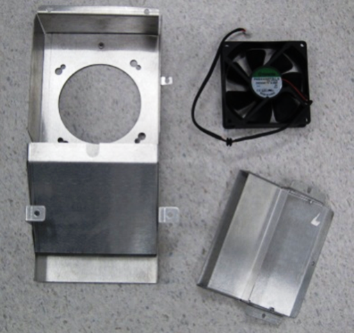
- DUCT 7 FAN KIT
- VAC HSG
- CHILLER RAMP
- Combination hex wrench set
- 4 mm long handle hex driver
- 5 mm long handle hex driver
- Flat blade screwdriver
- Hex driver set
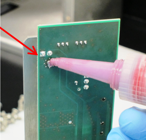
- Loctite 222 or 242
- Phillips head screwdriver
- Tubing cutter
- Zip ties
- VACUUM HOUSING
- PCB, VACUUM PLL CU
Time Required
- 2 hours
Procedure
- Put on proper PPE.
- Power down the Panther System.
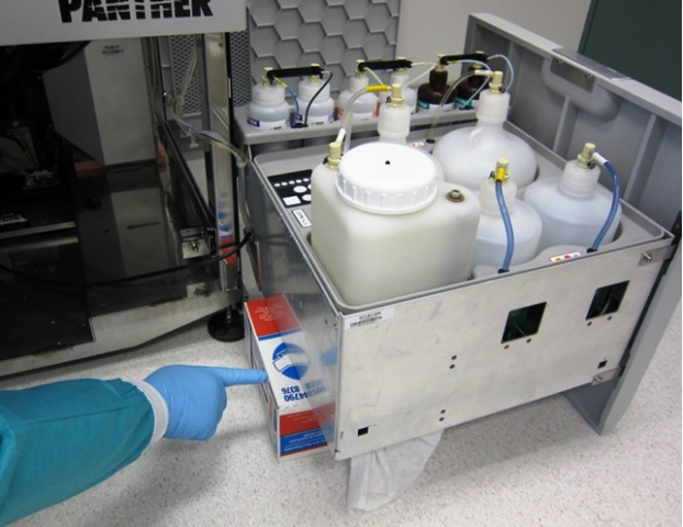
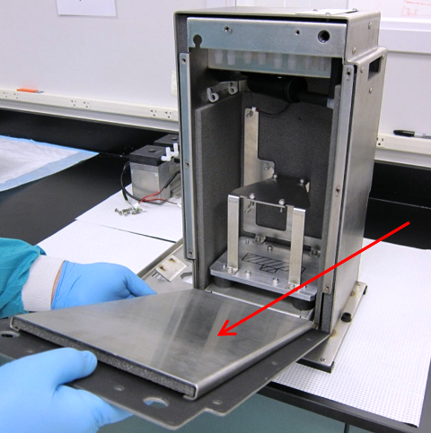
- Remove the Bleach, Wash Buffer, and Deactivation Buffer bottles from the Universal Fluids Drawer.
 Remove the Universal Fluids Drawer.
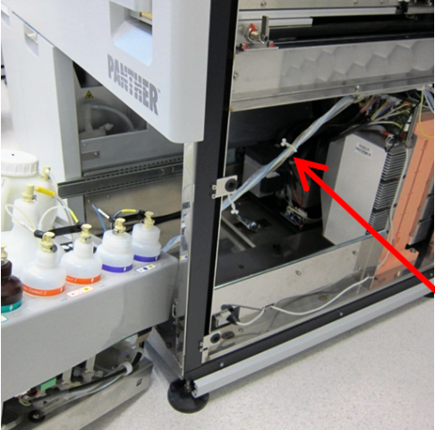
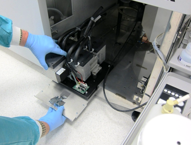
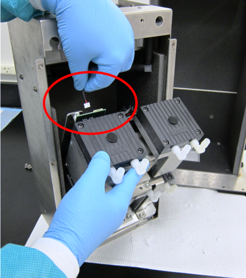
- Remove the Vacuum Module.

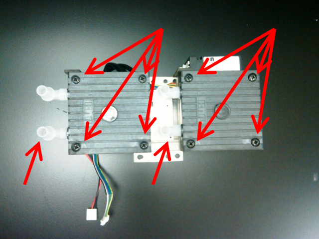
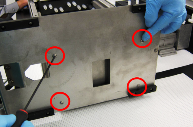
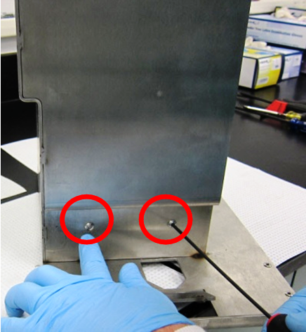
Note—Do not lift the Vacuum Module by the vacuum fittings. - Remove the vacuum pumps from the Vacuum Module base by removing the 8 mounting screws from the mounting feet of each of the pumps.
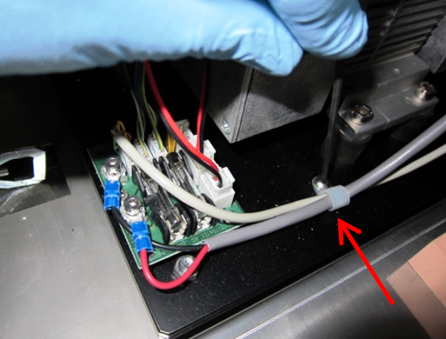
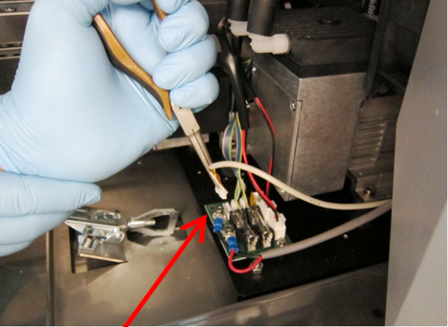
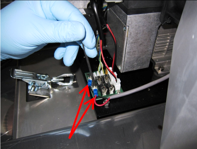
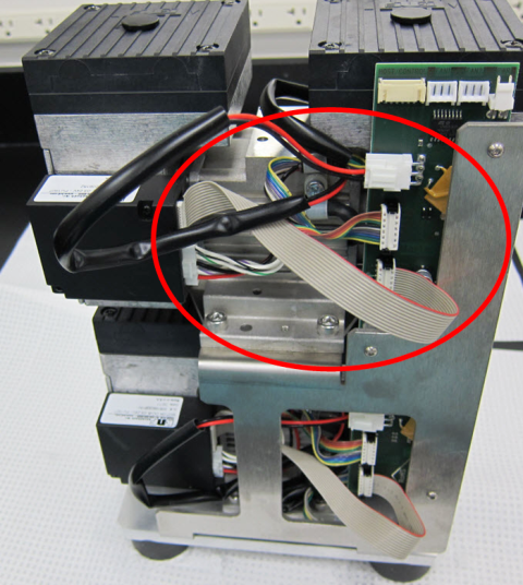
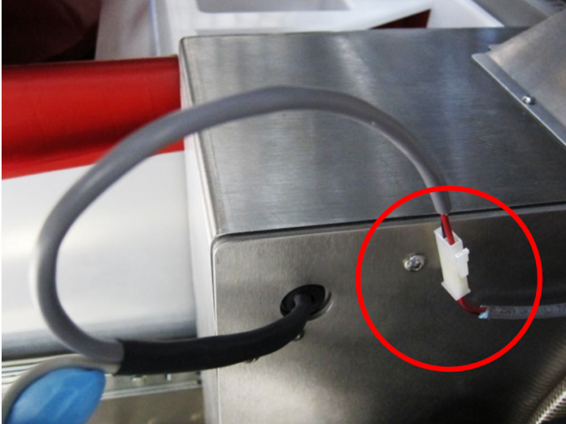
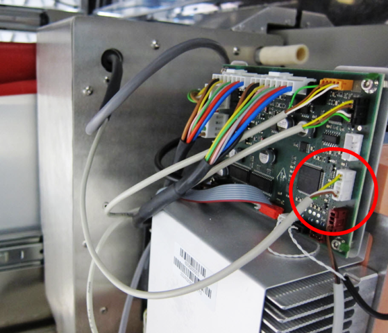
- Disconnect the power and control cables from the PCB.
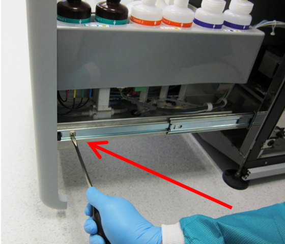
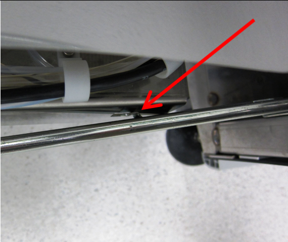
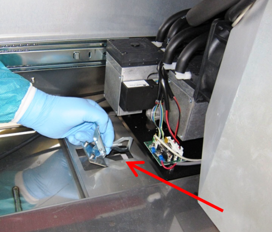
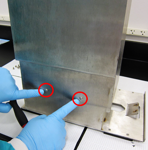
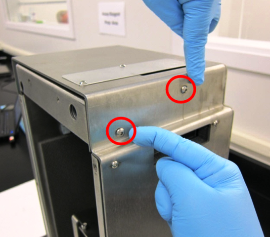
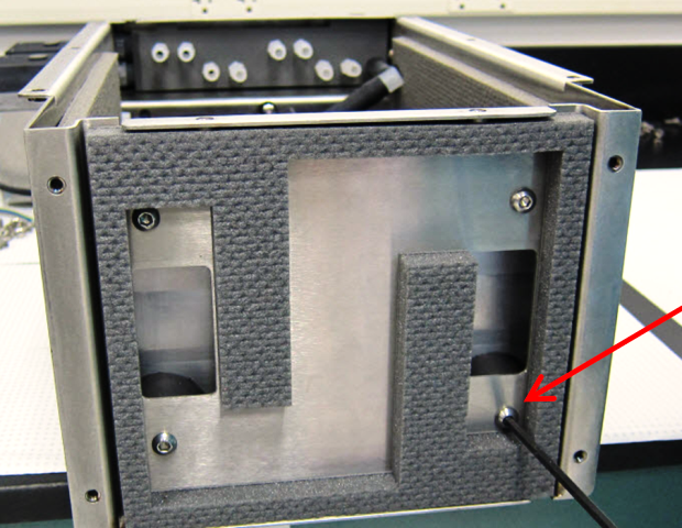
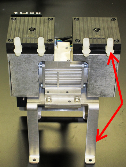
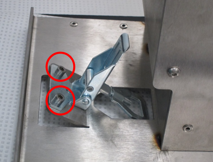
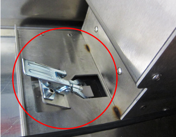
- Remove the buckle mechanism and its mounting screws. Do not discard the buckle and mounting screws—they will be used on the new housing.
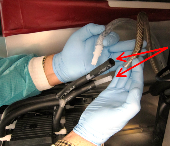
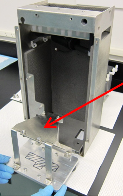
Note—Do not discard the original base. - Disconnect the black Norprene tubing sets from the pump head right-angle fittings.
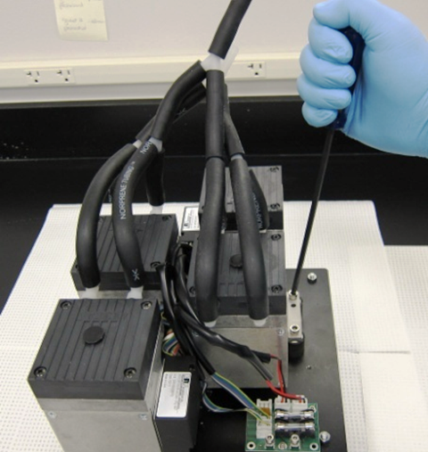
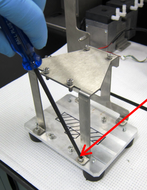
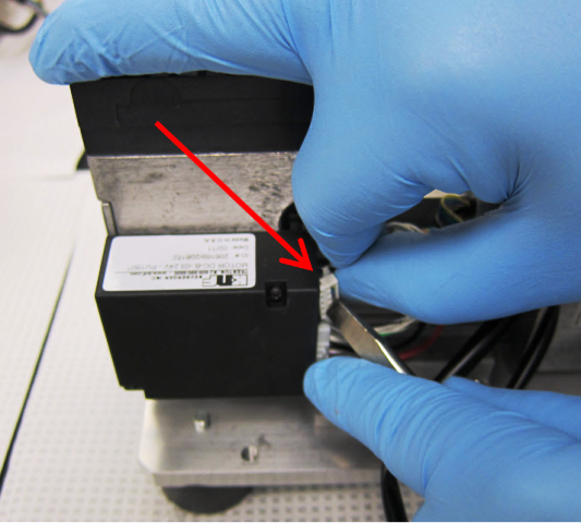
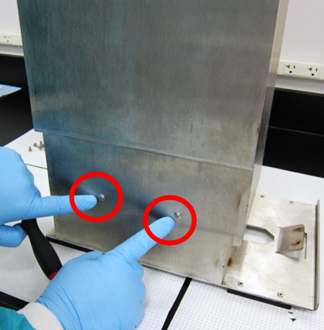
Note—Be very careful not to break the fittings on the head. - Remove the 4 pump head mounting screws on each of the vacuum pump heads.
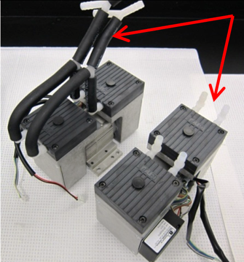
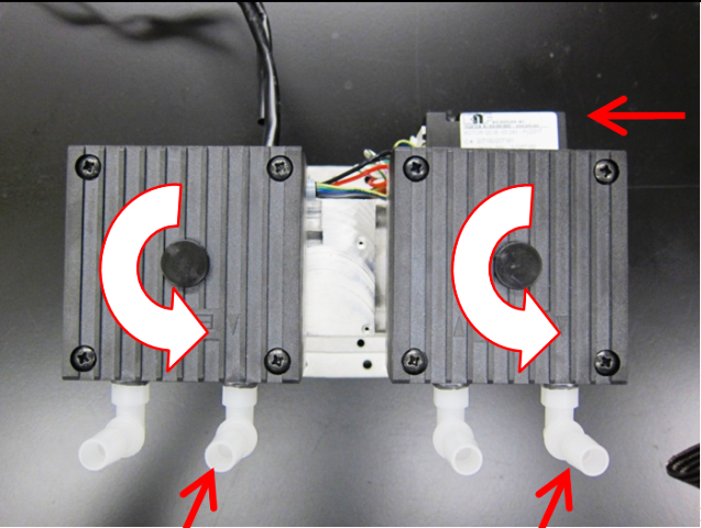
- Rotate the pump head 90° so that the input/output barbed fittings are opposite the pump controller. Perform this operation on both pumps. It is not necessary to disassemble the pump head by removing the center screw.
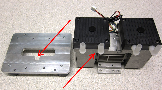
- Disassemble the new vacuum housing in preparation for installing the pumps.
- Using 4 M6X14 SHCSs, install one pump on the new housing pump base. Orient the pump so that the fittings are on the side of the notch T-shaped feature in the base. The pump controller should be on the opposite side.
- Prepare the cables.
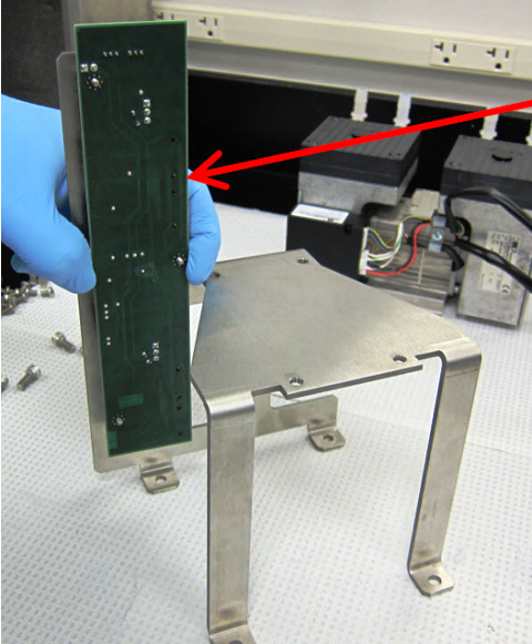
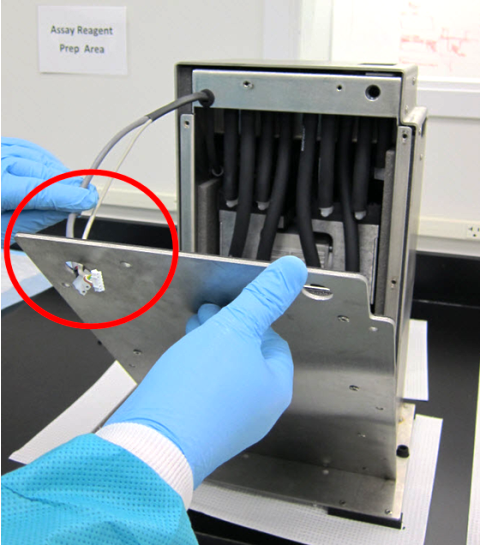
- Mount the new PCB.
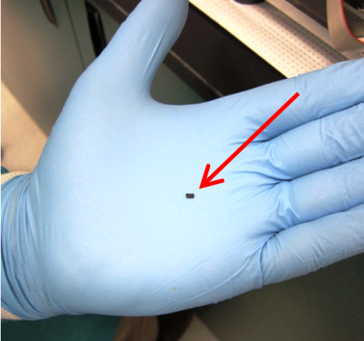
- Optional: Snap off the 8 connector locks to ease future servicing. The lock is a small flexure on the inside of the connector post that is easy to break off. Do not snap off the entire post—only the small flexure.
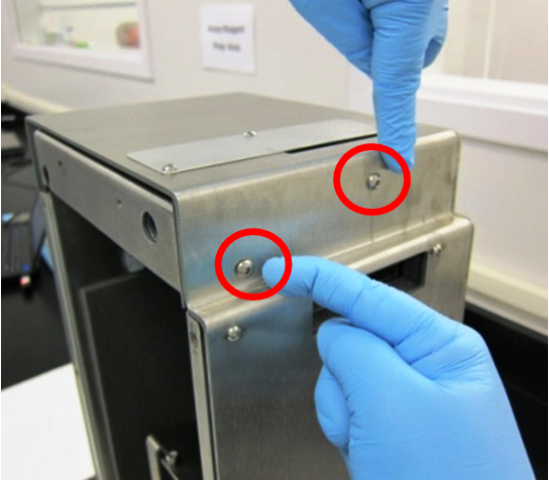
- Using 4 M6X14 SHCSs, install the upper pump onto the bracket. The fittings of the pump should face the skinny legs of the bracket.
- Install the mounting bracket and upper pump onto the pump base by vertically sliding the bracket over the lower pump. The upper pump should be oriented so that the inlet/outlet fittings are on the same side as the lower pump fittings. The bracket will have to be spread apart slightly to fit over the lower pump controller. Fasten the bracket to the base with 4 M6X14SHCSs.
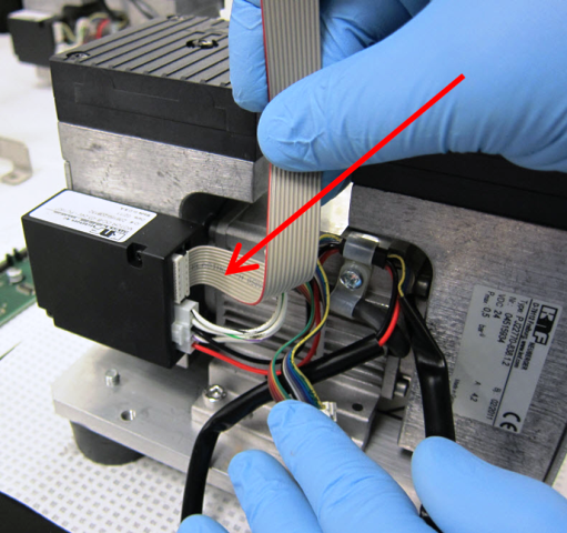
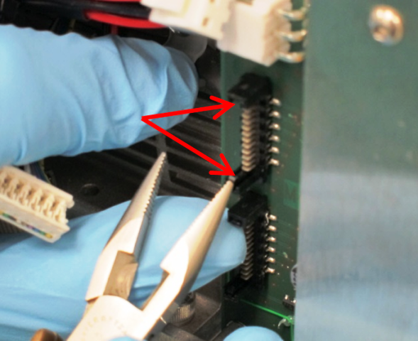
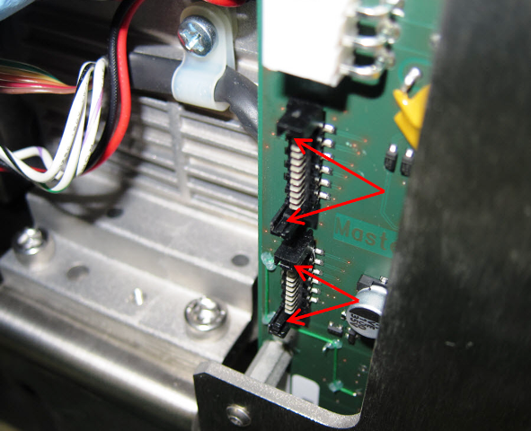
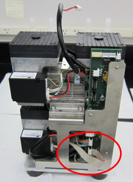
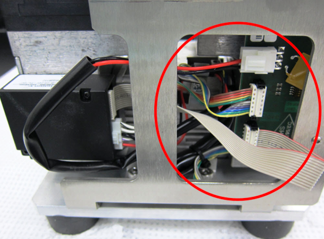
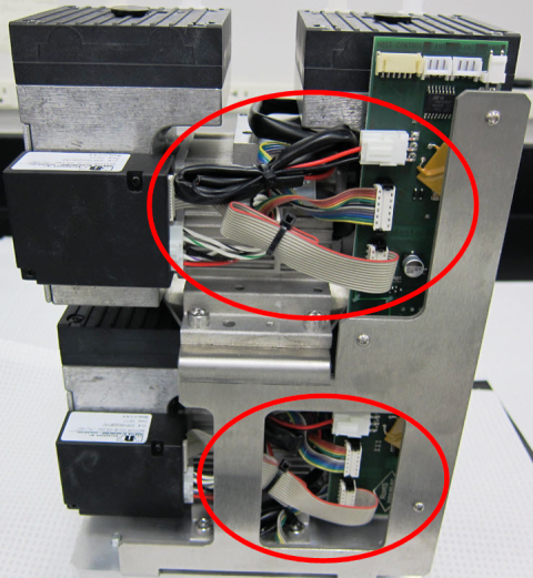
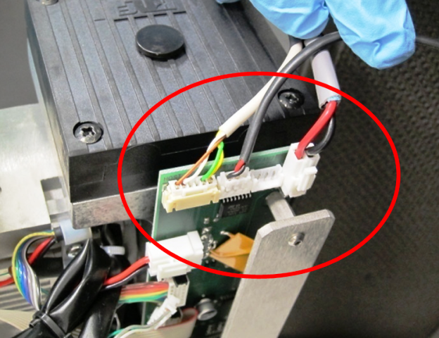
- Connect the ribbon cable from the pump and the new ribbon cable from the controller to the new PCB.
Note—Note how the new cable is flipped over to make the connection. The striped side of the ribbon cable is on the bottom at the pump control box, and then flips to the top at the PCB connector. The connectors are polarized with narrow and wide slots that match up to narrow and wide posts on the mating connector. Zip tie the cables so that they are tucked away neatly. - Load the vacuum pumps assembly into the inner housing.
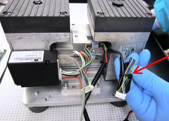
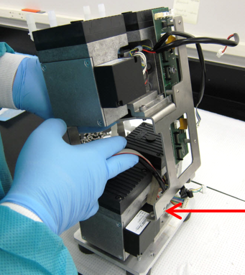
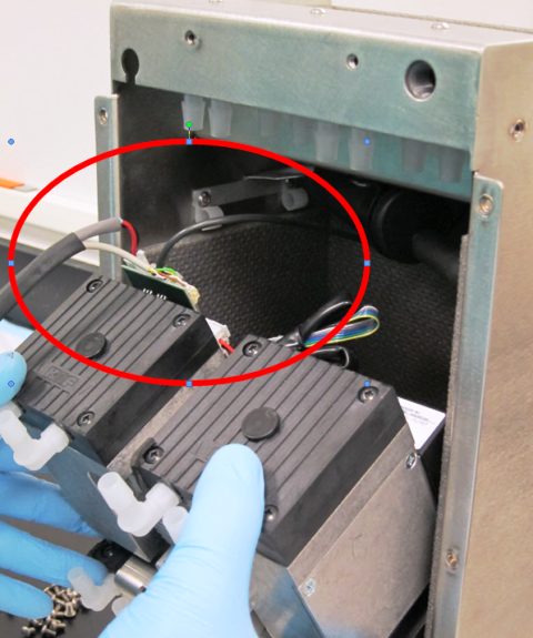
- Route the power cables.
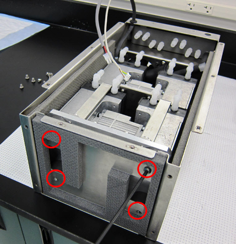
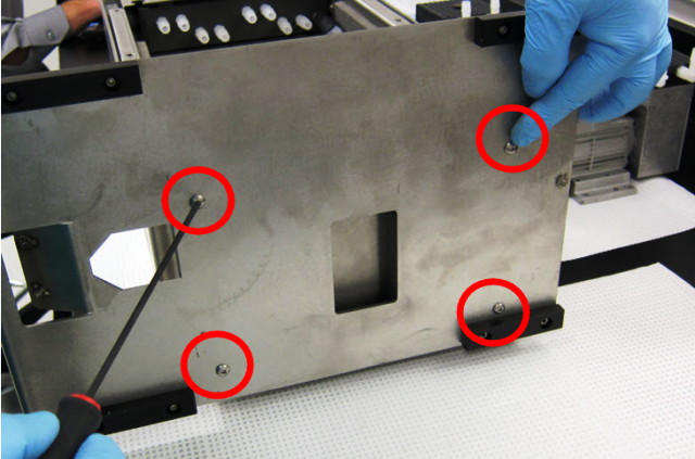
- Using a 4 mm Allen key, secure the stacked pump assembly into the inner housing with 4 M6X8 BHCSs from the bottom of the inner housing.
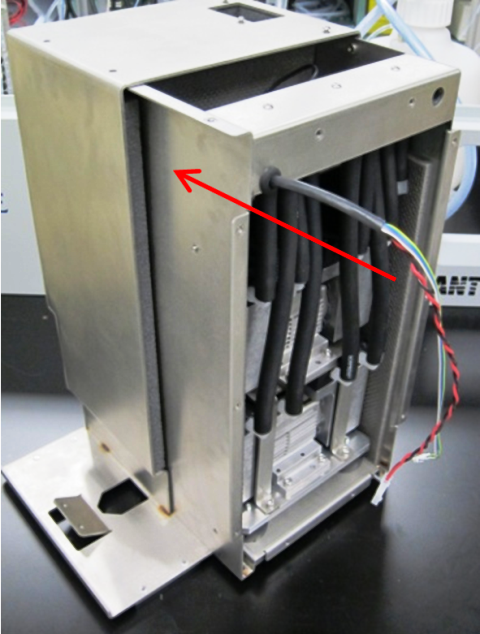
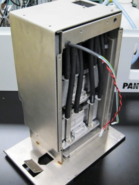
- Slide the inner housing into the outer housing. Be careful not to pinch your fingers.
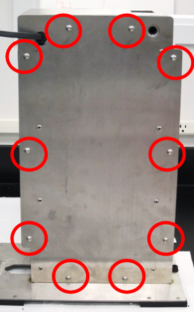
Helpful Hint—From this point forward, it is up to the discretion of the field engineer to move the installed vacuum housing to the floor by the system. This is to help prevent heavy lifting of the vacuum housing. - Using a 3 mm Allen key, secure the inner housing with 10 M5X10 BHCSs.
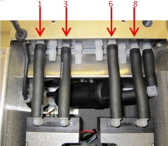
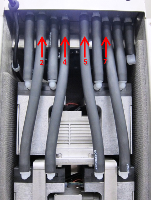
- Install 8 new pieces of black Norprene tubing from the pumps to the manifold.

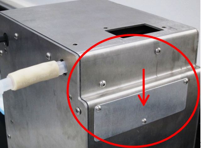
WARNING—Correct connection is critical. - Install the front cover.
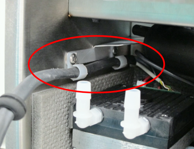
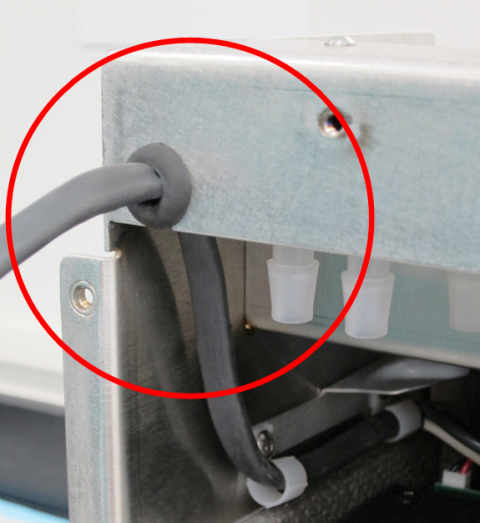
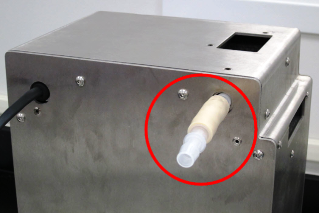
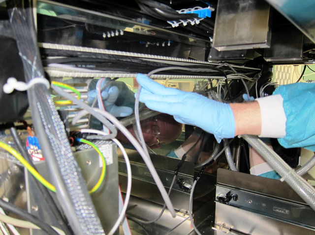
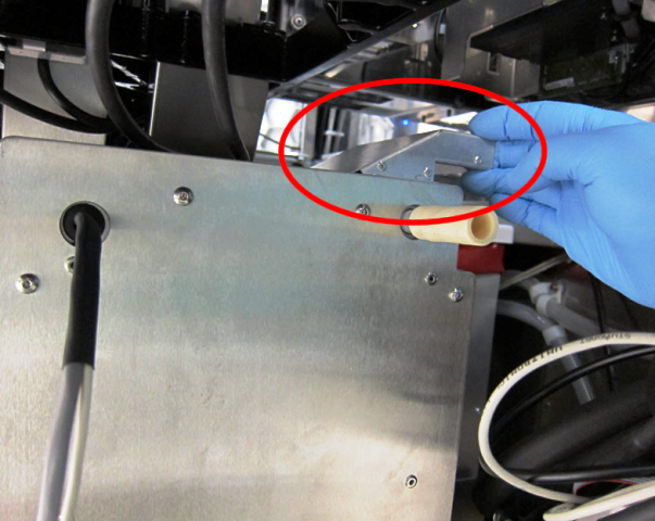
- Install the inlet tubing.
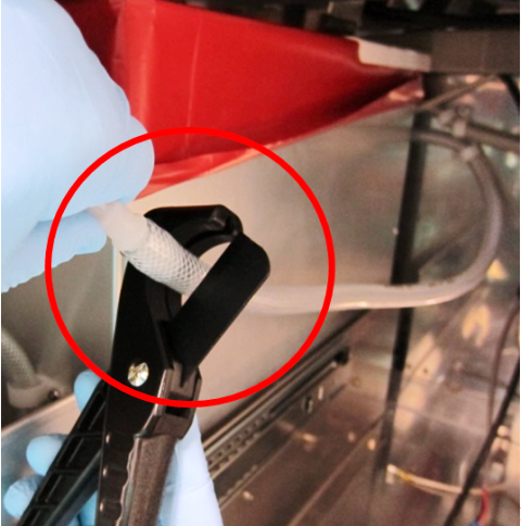
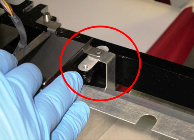
- Install the fitting assembly and buckle.
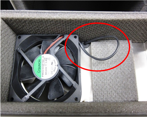
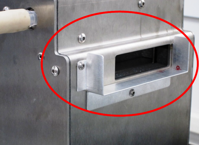
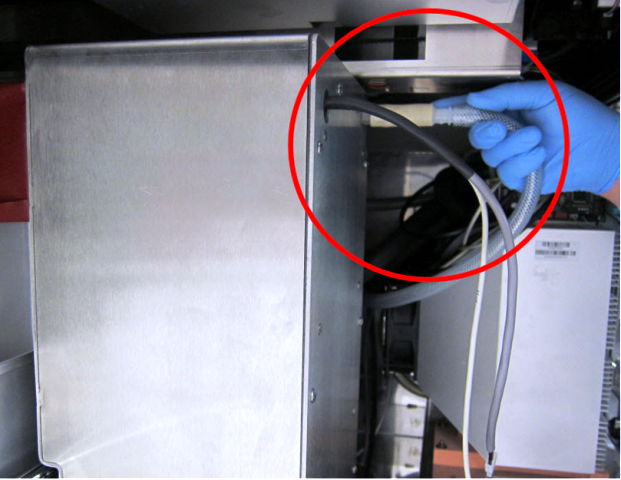
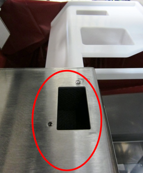
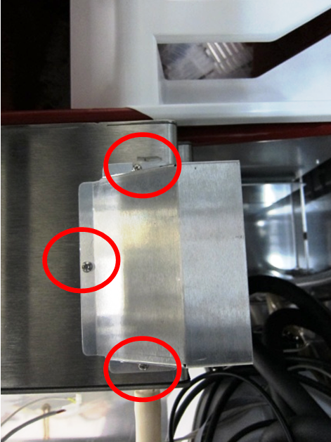
- Prepare the vent:
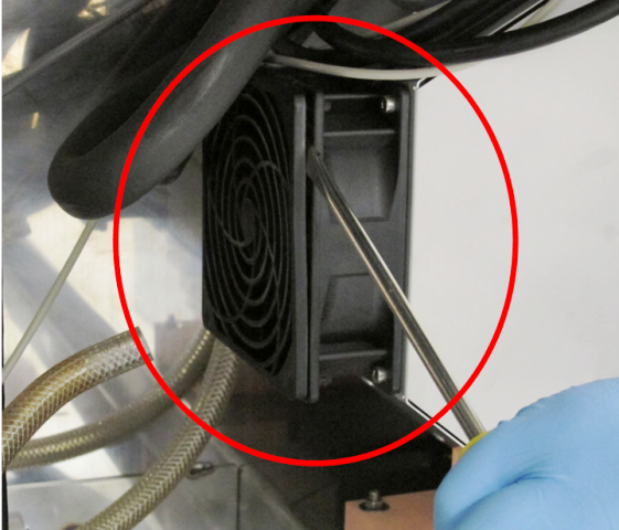
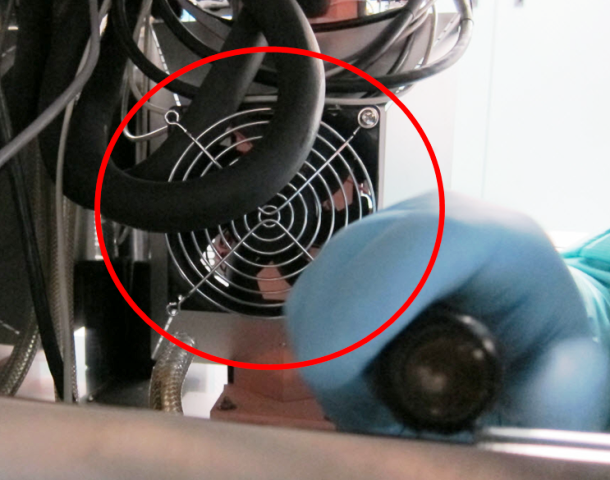
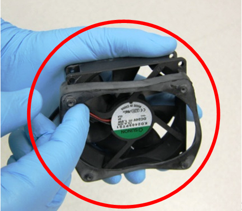
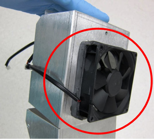
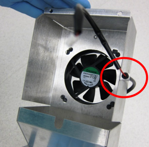
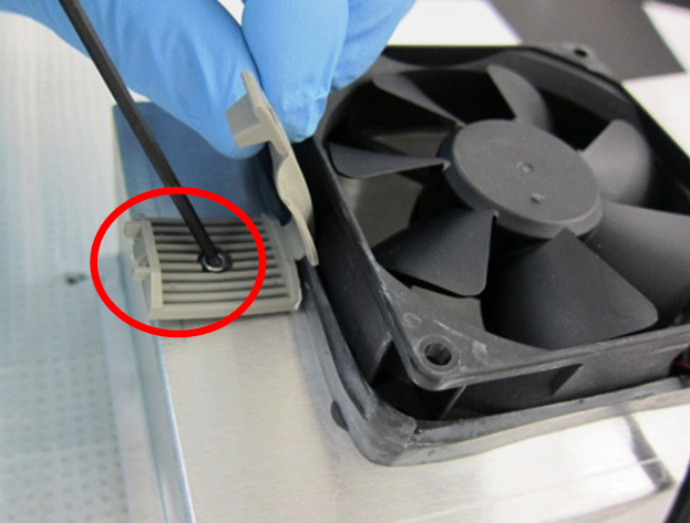
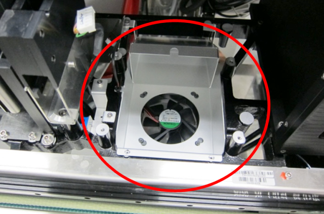
- Upgrade the fan guard on the Cooling Module.
- Prepare power for the new vacuum box. (It may be helpful to remove the power supply from the system.)
- Cut off the barbed fitting at the end of the tubing from the waste drawer and discard.
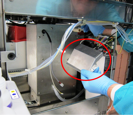
- Remove the existing (dual) muffler and exhaust tubing from the system. (The new vacuum box has an internal muffler and a new exhaust system.)
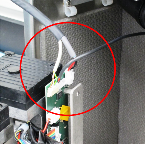
- Remove and discard the existing control cable between the pump and the Cooling Module PCB.
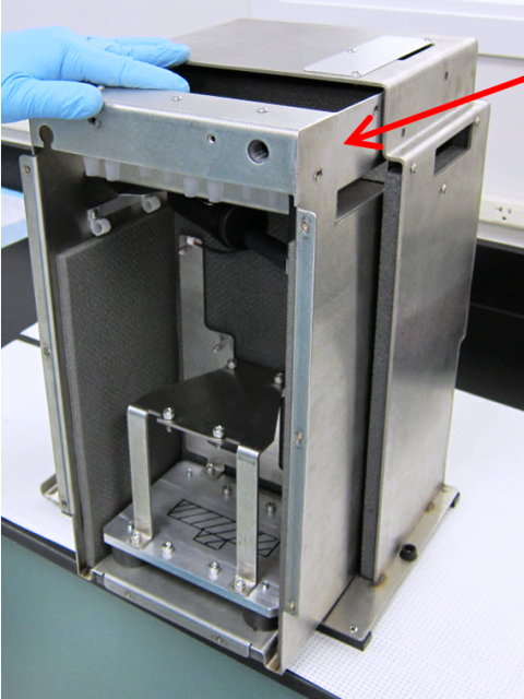
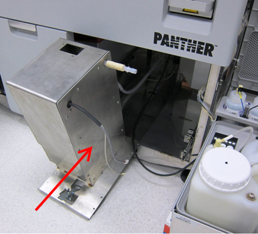
- For newer Panther Systems (Serial # 00281 and greater), no further system modifications are necessary. Install the new vacuum housing module with the rear vent already attached to the vacuum box.
|
|
Note—For older systems (Serial #s 00280 and lower), follow the instructions below for Chiller Ramp Upgrade for Older Panther Systems before installing the vacuum box. |
Chiller Ramp Upgrade for Older Panther Systems (Serial #s 00280 and lower)
- Reconfigure the Chiller Ramp for systems Serial #s 00280 and lower.
- Install the vacuum housing upper duct to share the Chiller Ramp vent with the new Chiller Ramp duct.
Verification
- Power on the Panther System.
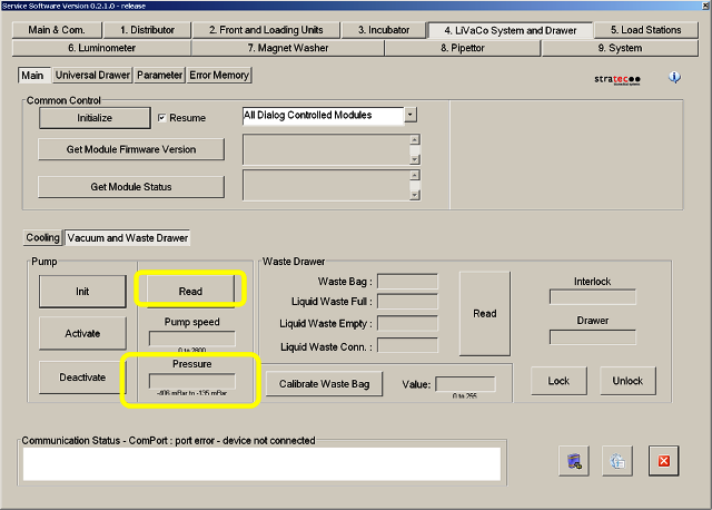
- In Service Software, check to see if the vacuum is running.
- Launch Service Software.
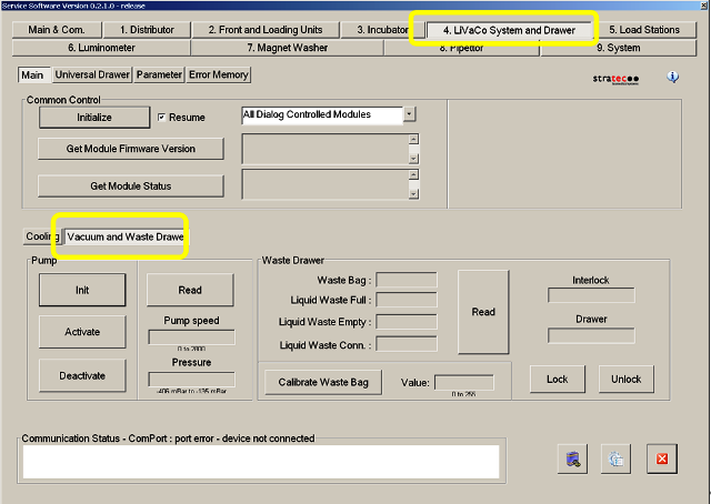
- In the LiVaCo System and Drawer tab, select Vacuum Waste Drawer.
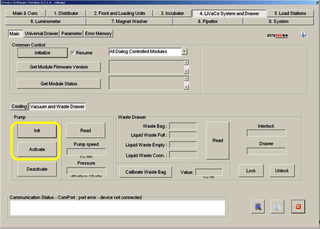
- In the Pump section, select Init and then Activate.
- Allow the system to run for at least 5 minutes.
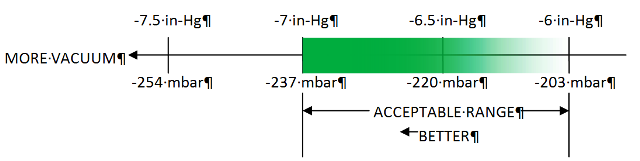
- To read the manifold vacuum level for each configuration, select Read in the Vacuum and Waste Drawer window.
- Make sure to re-optimize the Panther System ported manifold since the new vacuum box is a little more restrictive.
Start with the manifold cover port configuration with the lowest vacuum level so that the PID control system is not acting to control the vacuum level, and the pumps are forced to run at full speed. Increased airflow into the manifold through the ported manifold cover reduces the vacuum level. Therefore, the configuration that will result in the lowest vacuum level is the “both ports open” configuration (neither port plug screws installed), which should be the initial “as installed” configuration. The left port has a larger diameter air pathway than the right port. Therefore, the second configuration should be the “left port open, right port plugged” configuration followed by the “right port open, left port plugged” configuration. Finally, the “both ports plugged” configuration provides the highest vacuum level.
- Once the vacuum level is set correctly, the installation is complete.
- Using the Panther System Main software, perform a System PrimeOperation of pumping fluid through tubing to ensure proper and consistent fluid delivery (remove air from the tubing, etc.). to verify that the vacuum system functions properly during Magnetic Wash Station aspiration.
- Verification is complete.
 button at the top of the page to send feedback, comments, or change requests.