Parts and Materials Required
- Pipettor teach caps
- 2 mm Hex driver
- 3 mm Hex driver
- 4 mm Hex driver
- Large screwdriver
- TIP DRAWER, ASSY
Time Required
- 30 minutes
Removal Procedure
- Put on proper PPE.
- Remove the gantry shield by removing the two screws (optional).
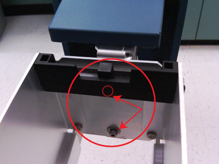
 Remove both of the Tip Drawer handles and the partition wall by removing the 3 mm screws as shown.
- Remove the Upper Bay front cover panel.
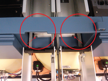
- Unscrew and remove the 4 mm screws shown below.

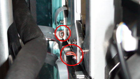
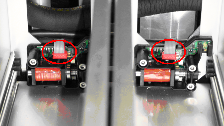
Note—The photo below shows the front cover in place. This is for reference only as the cover was removed in the previous step. - Remove the rubber bands that hold down each flex cable.
- Unplug the flex cable from the orange connectors.
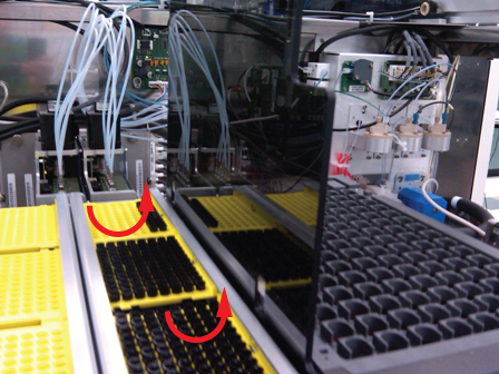
- Remove the Tip Drawer by carefully pulling the front of the Tip Drawer while carefully lifting the front end out towards the front of the system.
Note—If the module will be returned, clean the module.
Replacement Procedure
- Slide the rear brackets of the Tip Drawer into the fixed screws in the Upper Bay. If necessary, loosen the fixed screws a half or full turn with the screw driver
- Use the two 4 mm screws removed during the Removal Procedure to secure the Tip Drawer.
- Replace the Upper Bay front cover panel.
- Reattach both drawer handles using the screws removed in step 2 of the Removal Procedure.
- Replace the front cover.
- Reattach both drawer handles using the 3 mm screws removed in step 2 of the Removal Procedure.
Alignment/Calibration
Verification
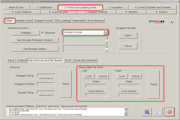
- Start up Service Software.
- Using Service Software, initialize the sample module and verify the Tip Drawers Sensors. Check the sensors are properly wired and work correctly. Use the Read button to verify the State of the drawer is correct by opening and closing the drawers individually.
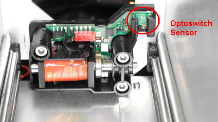
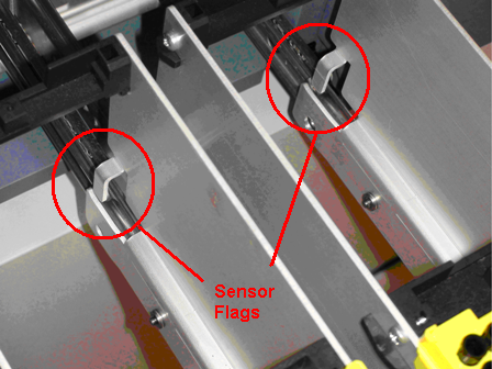
- Verify for each drawer the State corresponds to the position of the flag to optoswitch sensor when the flag in or out using the Read button.
- Verify Tip Drawers lock and unlock. With the left drawer in, lock the drawer. Verify the Lock Sensor reads locked using the Read button. Unlock the drawer and verify the Lock Sensor reads unlocked using the Read button. Do the same with the right drawer.
 button at the top of the page to send feedback, comments, or change requests.
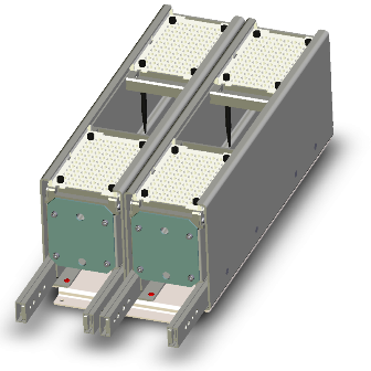