Upper Bay Front Cover Removal and Replacement
Parts and Materials Required
Time Required
Removal Procedure
- Put on proper PPE.
 Remove Left Corner Cover. This is a press-fit cover.
- Unplug the front panel connector located on the left side of the system.
- Remove both of the Tip Drawer Covers.
Using a 3 mm hex key, remove the two screws securing each Tip Tray Drawer covers.
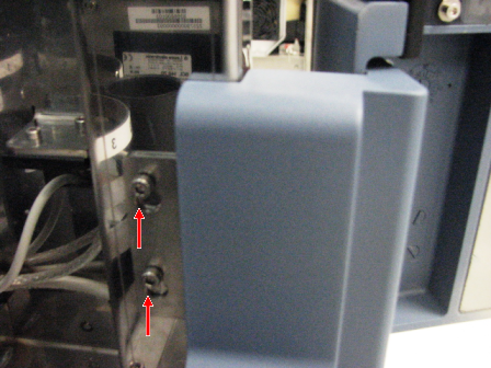
- Using a 2.5 mm hex key, remove the 3 screws located on either side of the Reagent Bay and on either side of the Tip Drawer.
- Partially slide out the Service Drawer. This will provide a surface upon which the front panel can rest when fasteners are removed.
- Open the door.
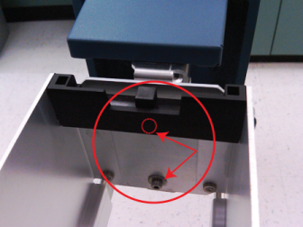
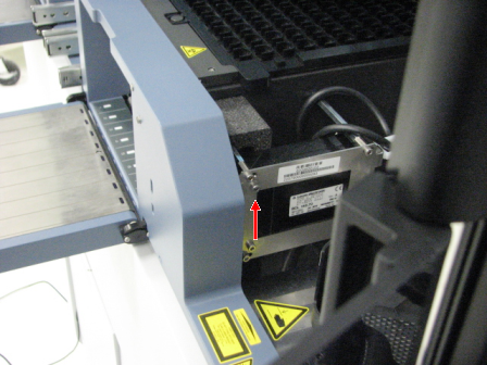
- Using a 3 mm hex key, loosen the second to the top screw by the TCR door that secures the front panel to the scanner bracket.
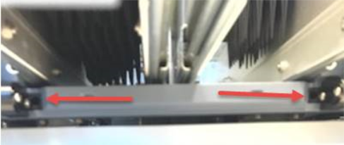
- Using a 3 mm hex key, remove the 2 screws at the left corner.
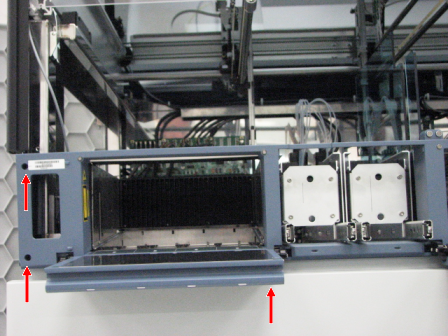
- While supporting the TCR door with your hand, use a 3 mm hex key to remove the 2 screws that secure the TCR panel door
- Allow the pin at the top of the TCR door to slide down out of the frame.
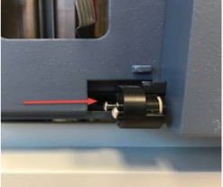
- Disconnect the 2 connectors by the TCR Carousel, and the 1 connector by the Sample Bay.
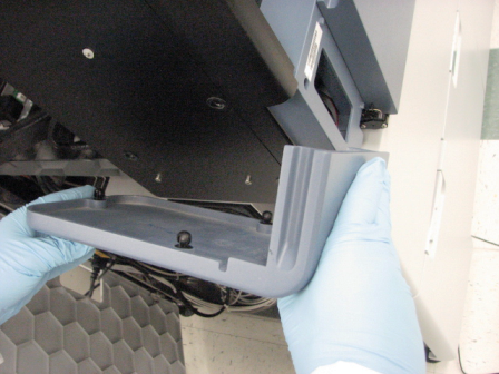
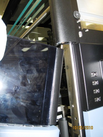
- Carefully remove the front cover and place on a stable surface.
Replacement Procedure
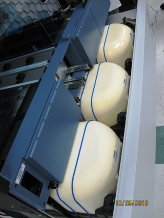
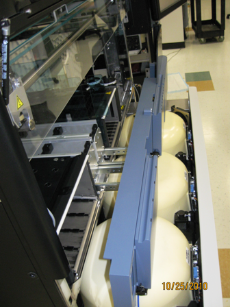
- With the Service Drawer partially open, rest the front cover on the Incubators.
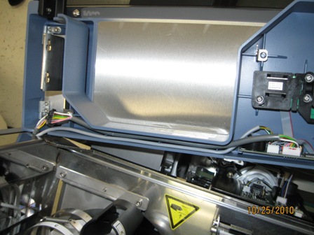
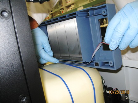
- Connect 2 connectors on the backside of the panel near the TCR door. Route cables as shown.
- Route flex cable on left side of drawer as shown.
- Route flex cable on left side of front panel through frame as shown.
- Angle front cover and lift up to slide TCR door pin into frame.
- Lift front panel into place.
- Using a 3 mm Allen wrench, install 2 mounting screws near TCR door.
- Using a 3 mm Allen wrench, make sure mounting tab is in place and tighten screw on sample scanner.
- Using a 3 mm Allen wrench, install 2 mounting screws on the left side of the front panel.
- Close the Service Drawer.
- Using a 2.5 mm hex key, install the 3 screws located on either side of the Reagent Bay and on either side of the Tip Drawer.
- Using a 3 mm hex key, install both screws securing the Tip Tray Drawer covers.
- Connect the front panel connector located on the left side of the system.
- Snap the press-fit left corner cover of the system.
Click the  button at the top of the page to send feedback, comments, or change requests.