Parts and Materials Required
- Allen wrench, 2.5 mm
- Allen wrench, 3 mm
- OUTPUT Q/LUMO, INJECT OLV/DISP VER PCB
Time Required
- 2 hours (includes re-teaching the Distributor and running an Operational Qualification [OQ])
Removal Procedure
- Put on proper PPE.
- Remove the Luminometer.
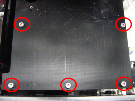
 Using a 3 mm Allen wrench, remove five of the ten screws that secure the Luminometer lid.
- Remove the remaining five Luminometer screws.
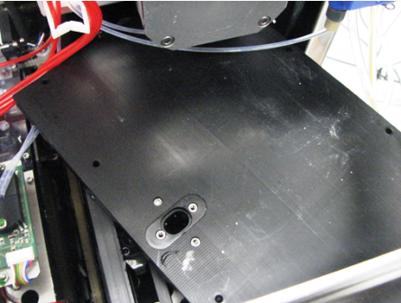
- Slightly rotate the lid and lift it up.

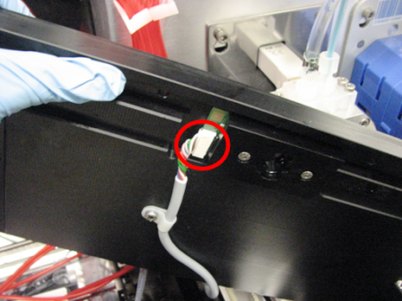
Note—There is a cable underneath the lid. - Unplug the cable to the Luminometer lid from the dispense verification PCB.
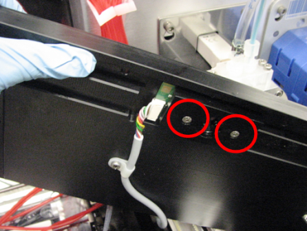
- Using a 2.5 mm Allen wrench, unscrew the two screws that secure the dispense verification PCB.
- Remove the dispense verification PCB.

Replacement Procedure
- Position the dispense verification PCB and, using a 2.5 mm Allen wrench, screw in the two screws that secure it to the Luminometer lid.
- Plug the cable into the Luminometer dispense verification PCB.
- Place the lid on top of the Luminometer.
- Insert and tighten the ten 3 mm screws that secure the Luminometer lid.
- Replace the Luminometer.
- Lower the pipettor door flaps.
- Start up Service Software.
 button at the top of the page to send feedback, comments, or change requests.
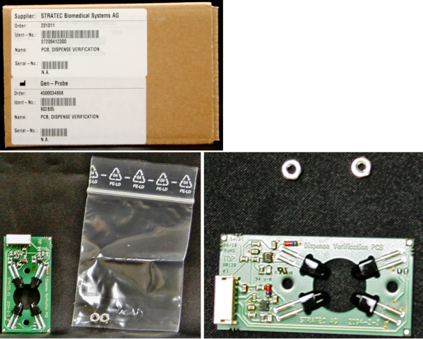