|
|
Laser Warning—This product utilizes internal barcode scanners with visible red laser light. Long term viewing of the laser light could result in eye damage. Never stare into the barcode scanner laser light. This is a Class 2 laser product in accordance to EN 60825-1: 2007 and complies with 21 CFR 1040.10 and 1040.11 except for deviations pursuant to Laser Notice N. 50, dated June 2007. |
Parts and Materials Required
- Proper PPE
- Hex key, 4 mm, long shaft
- MTU INPUT Q, MODULE
Time Required
- 20 minutes (does not include re-teaching the Distributor)
Removal Procedure
- Put on proper PPE.
- Shut down the Panther System and PC.
- Remove the Luminometer Injector.
- Carefully open the Service Drawer.
- Unscrew the Panther front cover.
- Set the cover and screws aside for re-installation.
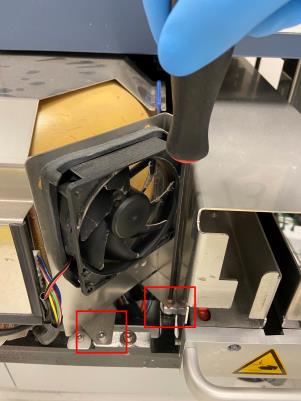
 Using a 4 mm hex key, remove the front and rear screws from the MTUMulti-tube unit—Container used to process tests in the instrument. An MTU contains five separate reaction tubes. The MTU is moved through the instrument by the linear distributor and includes five tiplets for pipettiing to be used in the mag wash station. Input Queue.
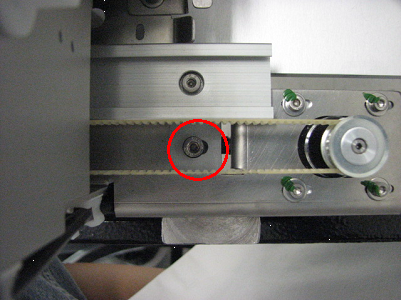
- Completely open the MTU Input Queue drawer to expose the center screw. Remove this screw.
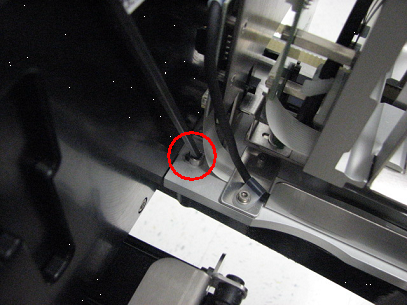
- Remove the MTU Input Queue's rear screw.
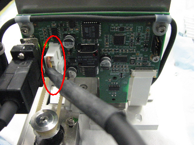
- Disconnect the CAN cable from the Master PCB.
- Remove the MTU Input Queue.

NOTE—If returning the module, decontaminate the module and complete the COD/OBF/RMA Form [19-02-APX-A].
Replacement Procedure
- Reverse the removal procedure.
- Verify that connections are properly seated and that screws are all in place.
- Load the Panther System firmware to the module.
 button at the top of the page to send feedback, comments, or change requests.