Fusion Tip Drawers Removal and Replacement

|
Note—A Firmware Installation procedure must be performed when replacing a module or PCB. |
Parts and Materials Required
- FSE Tool Kit
- Bench Top Pads
- Tip Drawer Module
Time Required
- 30 Minutes
Tip Drawers Removal Procedure
- Put on proper PPE.
- Remove all Tip Trays.
- Shut down the system and PC.
- Remove the Front Panel.
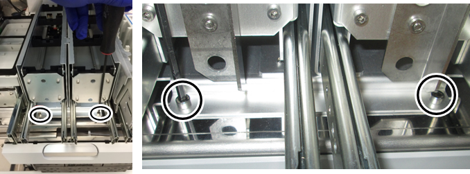
Refer to the Front Panel Removal and Replacement procedure. - Using a 4mm hex driver,
 remove the 2 front screws that secure the Tip Drawer module.
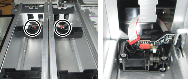
 - Disconnect the cable connector from the 2 solenoid locks. Note the connector orientation, the red stripe will go on the right when re-connecting.
- Remove the Tip Drawer by sliding it towards the front of the system.
- Place the Tip Drawer on a sterile benchtop pad.
Tip Drawers Replacement Procedure
- Reverse the Removal Procedure.
- Replace the Front Panel.
Refer to the Front Panel Removal and Replacement procedure.
Verification
- Power on the system and PC.
- Through Service Software, verify that all the Front Cover LEDs and drawer locks are working properly.
- Teach the Fusion Pipettor (right) to the Tip Drawer.
Refer to Service Procedures > Panther Fusion System Pipettor Teaching. - Perform a Sidecar Pipettor OQ Test.
Refer to Service Procedures > Side Car Pipettor OQ Test. - 7 cycles
- DiTi only (uncheck Cap & Vial)
- Check the Report, Initialize, and Shutter checkboxes only
 button at the top of the page to send feedback, comments, or change requests.