Fusion Front Panel Removal and Replacement

|
Note—A Firmware Installation procedure must be performed when replacing a module or PCB. |
Parts and Materials Required
- FSE Tool Kit
- Bench Top Pads
Time Required
- 15 Minutes
Front Panel Removal Procedure
- Put on proper PPE.
- Power down the Panther System and PC.
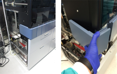
 Remove the corner cover.
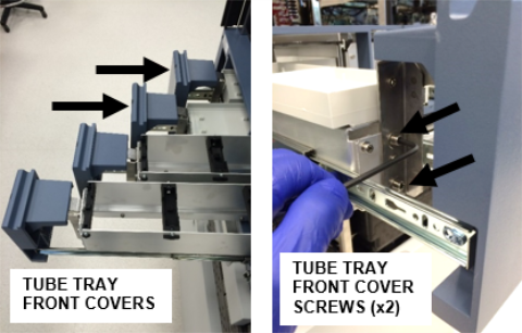
- Using a 4mm hex driver, remove the two Reaction Tube Tray front covers.
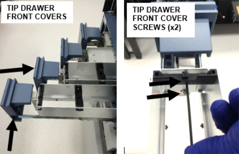
- Using a 3mm hex driver, remove the two Tip Drawer front covers.
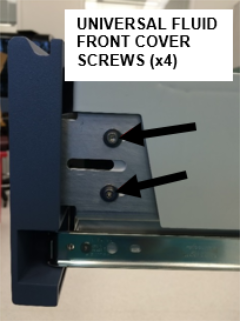
- Using a 3mm hex driver, remove the Universal Fluid Drawer front cover.
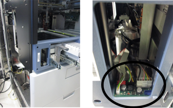
- Disconnect the 4 connectors located in the left side of the Front Panel.
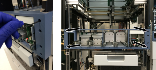
- Using a 3mm hex driver, remove the 4 screws that secure the Front Panel.
- Place the Front Panel on a sterile benchtop pad.
Front Panel Replacement Procedure
- Reverse the Removal Procedure.
- Ensure that the top of each drawer front cover is aligned with the top of the Front Panel and are evenly spaced.
Verification
- Power on the Panther System and PC.
- Load firmware to the new module (Instrument Setup).
Refer to Panther Fusion System Installation > Run Instrument Setup (Fusion). - Through Service Software, verify that all of the following components work properly:
- All front Panel LEDs
- Open/Close Sensors for all 5 front panel drawers
- Lock mechanism for all 5 front panel drawers
- Left System Status LED
- Waste Lock
- Waste Bag Presence sensor
 button at the top of the page to send feedback, comments, or change requests.