Thermocycler Moog Slip-Ring Removal and Replacement
Parts and Materials Required
- Panther Tool Kit
- 2x FUSION, THERMOCYCLER, WIRE HARNESS, SLIP RING
Time Required
Procedure
- Prepare a clean workspace covered with pads.
- Power on the Panther System and PC.
- Start Panther Main and allow the system to initialize.
- Check to make sure that all MTUs are cleared from the system and all vials are removed from the Thermocycler.
- Shutdown the Panther System and PC.
- Remove the Thermocycler from the Panther Fusion System.
- Place the Thermocycler on the work space that you prepared in Step 1.
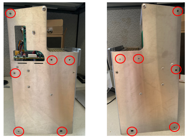
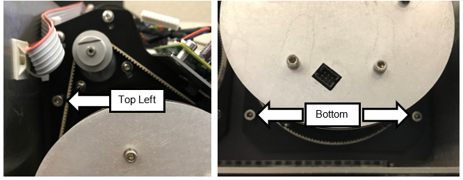
 Remove and save the 12 screws shown below.
There are 6 screws on the left and 6 screws on the right.
- You may need to remove the Thermocyler's handle
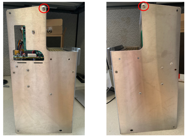
- Remove the rear of the Thermocycler housing, by gently tilting the bottom out and up.
- Lay the Thermocycler on its face to expose the internal components.
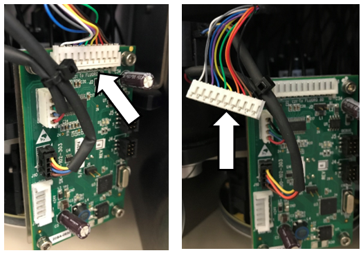
- Unplug the two 6-pin connectors (gray and pink ribbon cables) from the Fluorometer SCM Boards.
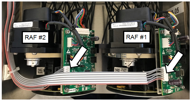
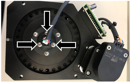
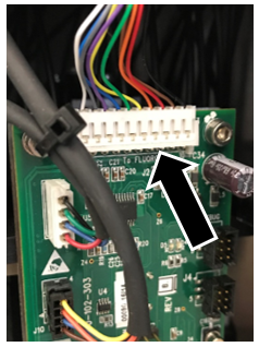
- Unplug the two 10-pin connectors (see picture below) from the Fluorometer SCM boards.
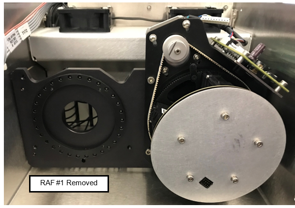
- Remove the three (3) M4 screws securing the Fluorometer RAF #1 to the Reformatter base plate. These are accessed from the bottom of the Thermocycler.

|
Note—Save the screws for reassembly. |
- Carefully slide the Fluorometer RAF #1 out of the base plate and set aside.
|
|
Note—Make sure that the 10-pin connector does not pull on the fiber optic cables when removing the Fluorometer assembly, as this can damage the cables. |
- Remove the three (3) M4 screws securing the Fluorometer RAF #2 out of the base plate and set aside
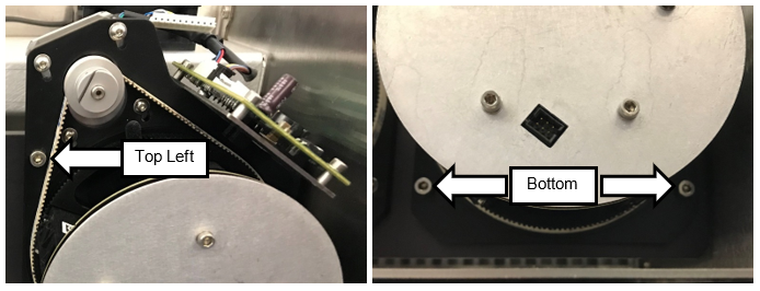
- Carefully slide the Fluorometer RAF #2 out of the base plate and set aside
| Note—Make sure that the 10-pin connector does not pull on the fiber optic cables when removing the Fluorometer assembly, as this can damage the cables. |
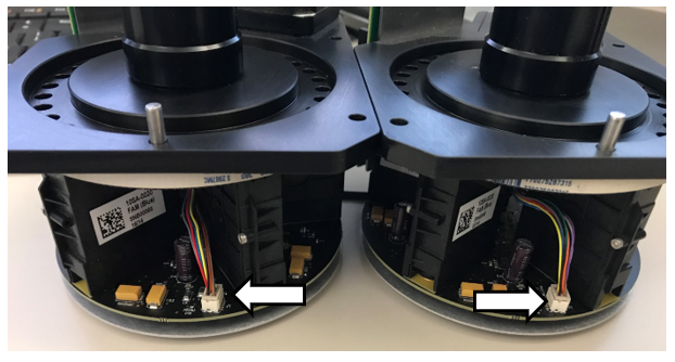
- Place the Fluorometers on the bench, resting on the aluminum base plate protection the RAF PCB.
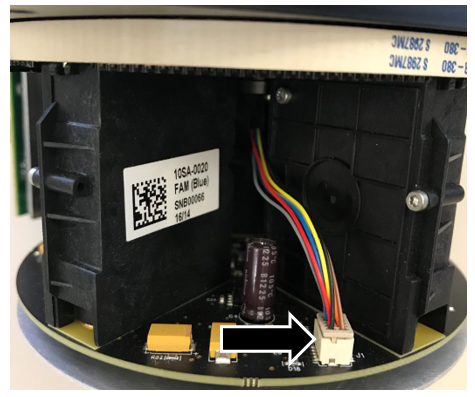
- Disconnect the Slip-Ring square connector of each RAF Board, located between the FAM and Hex Fluorometers.
- Remove the three (3) M2.5 screws and lock washers securing the Slip-Rings to the Slip-Ring Adapter plates to each Fluorometer.
| Note— Save the screws and lock washers for reassembly. |
- Slide the cable connected to the Slip-Ring out of the RAF assembly.
- Set aside the Slip-Ring Adapter plate for reassembly.
- Obtain the two replacement Slip-Rings.
- Attach the Slip-Ring Adapter plates to the new Slip-Rings with the three (3) M2.5 screws and lock washers.
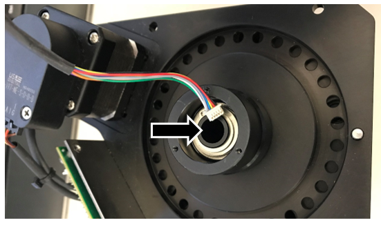
- Slide the 10-pin connectors into the hole on top of the RAF assembly.
- Connect the 10-pin square connectors to the RAF Boards.
- Feed the 10-pin connector through the hole in the Reformatter base plate.
|
|
Note—Make sure that the 10-pin connector does not put pressure on the fiber optic cables when inserting the Fluorometer assembly in the next step. |
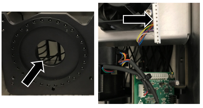
- Connect the 10-pin connector to the RAF SCM Board.
- Slide and seat the Fluorometer assembly against the Reformatter base plate, making sure to verify that the Fluorometer is flush against the Reformatter base plate.
- Using the three (3) M4 screws to secure Fluorometer RAF #2.
- Repeat for RAF #1.
- Connect the 6-pin connectors (gray and pink ribbon cable) to the Fluorometer SCM Board.
- After both Slip-Rings have been replaced on each of the RAF assemblies, install the back cover using the eight (8) M4 BHCSs.
- Reinstall the Thermocycler into the Panther Fusion System.
- Discard the old Slip-Rings.
Verification
- Power on the system and the PC.
- Teach the Vial Robot to the Thermocycler module.
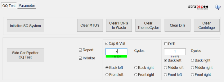
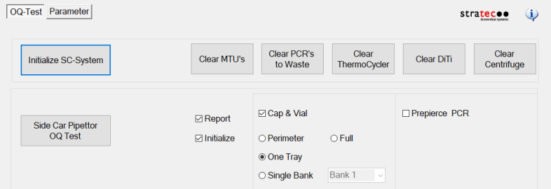
- Perform a Sidecar Pipettor OQ Test.
- For Service Software v4.0.7.0
- Check Cap & Vial only (uncheck the DiTi check box)
- Set 7 cycles
- For Service Software v5.0.12.0
- Check Report
- Check Initialize
- Check Cap & Vial
- Select One Tray
- Save report and remove any used partial tray(s) when complete.
Click the  button at the top of the page to send feedback, comments, or change requests.