Parts and Materials Required
- 2.5 mm Allen wrench
- 3 mm Allen wrench
- CHILLER RAMP, PELTIER MODULE
Time Required
- 30 minutes (does not include re-teaching the Distributor)
Removal Procedure
- Put on proper PPE.
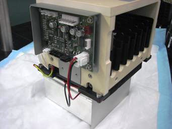
- Remove the Chiller Ramp.
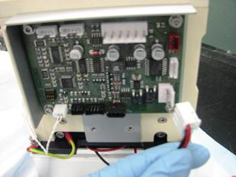
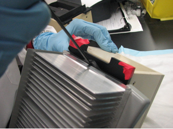
 Unplug the Peltier cable from the Chiller Ramp control PCB.
- Remove the drip pan from the Chiller Ramp.
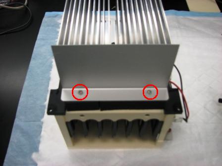
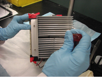
- Using a 2.5 mm Allen wrench, remove the two screws that secure the Peltier shroud and remove the shroud.
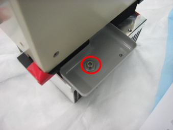
- Using a 3 mm Allen wrench, unscrew the three screws that secure the Peltier to the Chiller Ramp. Two of the screws are located underneath the Chiller Ramp foam.
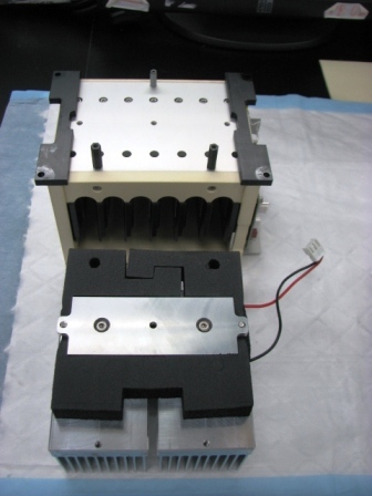
- Remove Peltier assembly, with foam, from the Chiller Module.
Replacement Procedure

|
New Peltier will be supplied with foam and center mounting screw. Use the two outer mounting screws removed above. |
- Make sure mating surfaces of the Peltier assembly and the Chiller Ramp assembly are clean.
- Install the Peltier assembly to the mating surface of the Chiller Ramp.
Make sure no foam is between the metallic interface surfaces. - Using a 3 mm wrench, screw in the three Peltier mounting screws.
- Replace the Peltier shroud and, using a 2.5 mm Allen wrench, screw in the two mounting screws.
- Replace the drip pan and secure.
- Plug the Peltier cable into the Chiller Ramp control PCB.
- Replace the Chiller Ramp.
 button at the top of the page to send feedback, comments, or change requests.
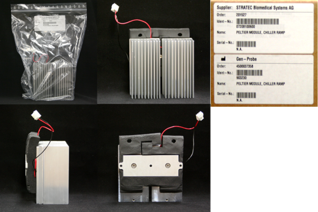