Parts and Materials Required
- 2.5 mm Allen wrench
- CHILLER RAMP, PCB
Time Required
- 30 minutes (does not include re-teaching the Distributor)
Procedure
- Put on proper PPE.
- Remove the Chiller Ramp.
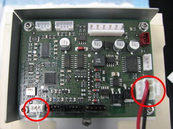
 Unplug the Peltier and temperature sensor cables from the Chiller Ramp control PCB.
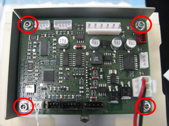
Caution — Use special care when disconnecting the sensor connector. DO NOT pull on fragile sensor wires. - Remove the four screws that secure the control PCB.
Replacement Procedure
- Tighten the four screws that secure the control PCB to the Chiller Ramp.
- Plug the Peltier and temperature sensor cables to the Chiller Ramp control PCB.
- Replace the Chiller Ramp.
- Run Instrument Setup (Loading Firmware)
 button at the top of the page to send feedback, comments, or change requests.
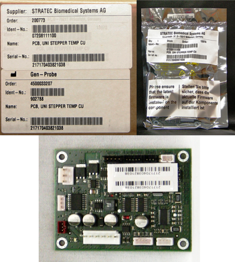