Luminometer Transport Drive Alignment Procedure
Parts and Materials Required
Time Required
- 60 minutes (if Syscheck is necessary)
- 3 hours (if teaching is necessary)
Procedure
- Put on proper PPE.
- Power off the Panther System, but leave the PC on.
 Disconnect the ribbon cable from the Luminometer PCB. If necessary, safely open the Service Drawer.
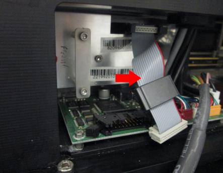
- Power on the Panther System.
- Login to the FSE Shield and start Service Software.
- Load at least one into the Input Queue.
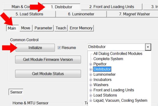
- From the 1. Distributor tab, select Main. Initialize the following modules:
- Select Distributor from the Common Control dropdown menu and click Initialize.
- Select Front and Loading Units from the dropdown menu and click Initialize.
- Select Luminometer from the dropdown menu and click Initialize.
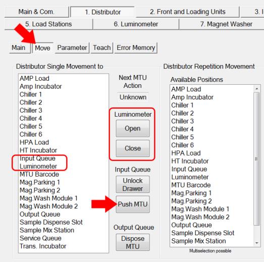
- Place an MTU into the Luminometer:
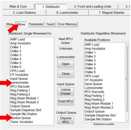
- From the 1. Distributor tab, select Move.
- Open the Luminometer door by clicking Open.
- Click Push MTU (ensure at least one MTU is loaded in the Input Queue).
- Double-click Input Queue on the Distributor Single Movement List to pick an MTU.
- Double-click Luminometer to place the MTU.
- Click Close to close the Luminometer door.
- Open the Service Drawer.
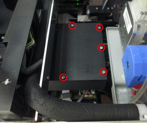
- Remove the Luminometer top cover:
- With the Service Drawer fully open remove the 5 screws that are visible (3mm hex driver).
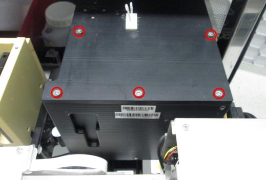
- With the Service Drawer about half-way closed, remove the other 5 screws that can be seen between the Carousel and the peristaltic pump.
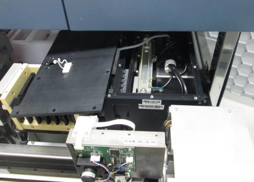
- Carefully move the Luminometer cover aside and rest it on the Chiller Ramp. Do not strain the cables that are attached underneath the lid.
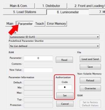
- From the 6. Luminometer tab, select Parameter. Enter 1 in the Authorization Code field and click Set.
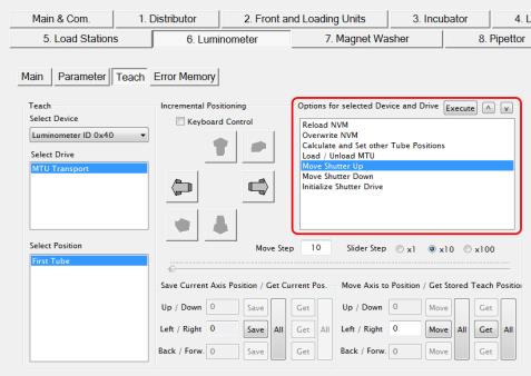
- Select Teach. Click the Get button in the “Move axis to Position/Get Stored Teach Position” section on the bottom right of the screen.
 | Note—Left / Right value should be between 1270-1320. |
- Click the Move button.
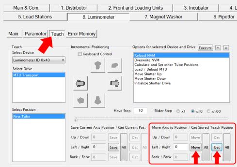
- The transport drive will move Tube 1 of the MTU above the injection location.
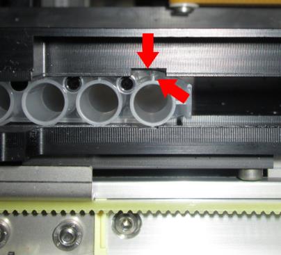
| | | Note—The tab on side of Tube 1 (tube at the back, near the barcode) should be lined up inside the cut out of the Lumo frame. The tab does not need to be exactly in the center. |
- Check the shutter alignment.
| |
|
Note—Watch the MTU when moving the shutter. The MTU should not move while the shutter is opening or closing. |
- Select the Move Shutter Up from the “Options for selected Device and Drive” menu and click Execute.
- Select the Move Shutter Down and click Execute. Repeat to evaluate movement.
- The MTU should not move during shutter movement. Even slight movement of the MTU means the MTU needs to be correctly aligned over the shutter.
- If there is any MTU movement, proceed to Step 16 and align the Transport Drive. Otherwise, proceed to Step 17.
- Align the Transport Drive.
| | | Note—You will only teach to Tube 1, all remaining tubes will be calculated. |
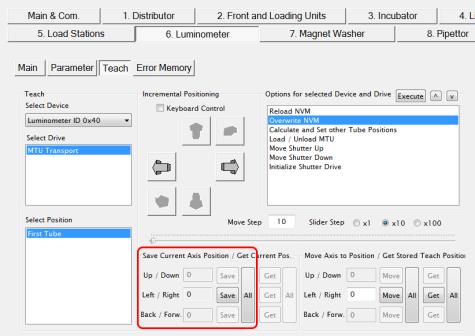
- Click on the right and left arrows in the “Incremental Positioning” section to move the MTU tab closer to the center of the cutout.
- Save the coordinate by clicking the Save button under the “Save Current Axis Positions/Get Current Pos.”
- Go back to Step 14 to check the shutter alignment again.
- If no alignment was necessary, proceed to the Verification section. If teaching coordinates were changed, save the new position. Under “Options for selected Device and Drive”:
- Select Overwrite NVM then click Execute. (Select Yes at all prompts.)
- Select Calculate and Set other Tube Positions then click Execute.
- Select Overwrite NVM then click Execute.
Verification
- With the Luminometer cover off, verify all five tube positions on the MTU are aligned properly with the shutter:
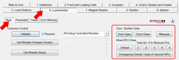
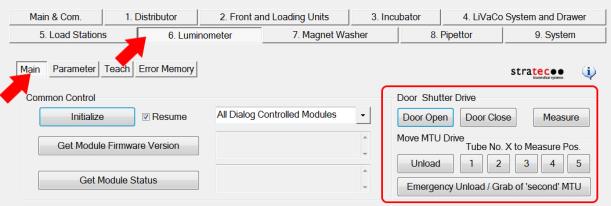
- From the 6. Luminometer tab, select Main.
- Under “Move MTU Drive”, select Tube No. 1 and then Measure. Verify the MTU does not move during shutter movement.
- Repeat Step 1b. for all 5 MTU positions. (Select Tube No. 2 and then Measure, etc.)
- If the shutter is moving freely, go to Step 2. Otherwise go back to Steps 15-17 in the Procedure section and align the shutter again.
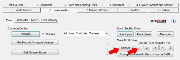
- Unload the MTU in the Luminometer:
- Select Tube No.1 and click Unload.
- From the 1. Distributor tab, select Move.
- Double-click Luminometer on the Distributor Single Movement List to pick the MTU.
- Double-click Service Queue to discard the MTU.
- Re-install the luminometer cover:
- With the drawer fully open finger tighten the first set of 5 screws all the way down to the lid.
- With the drawer partially closed finger tighten down the second set of 5 screws down to the lid.
- Now with the 3 mm screw driver tighten down all the 10 screws. You will need to fully open and partially close the drawer to get to all the screws.
- Power down the Panther System.
- Reconnect the PMT ribbon cable to the Luminometer PCB.
- Close the Service Drawer.
- Perform the following procedures:
- Lumo OQ using Service Software
- Darkcount test using Service Software
- If teaching coordinates were changed in the Procedure, Steps 14-16, perform the following procedures:
- Perform a Panther Luminometer Syscheck Reagent Verification procedure.
Click the  button at the top of the page to send feedback, comments, or change requests.