Parts and Materials Required
- VACUUM PCB
Time Required
- 60 minutes
Removal Procedure
- Put on proper PPE.
- Remove the vacuum module and place on a sterile, clean workbench.
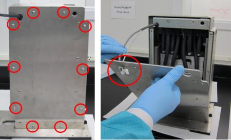
- Remove all ten M5x10 screws from the front cover.
 Remove the front cover from the housing (carefully guide the cables through the hole in the upper left corner of the cover).
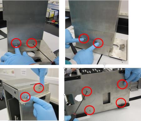
- Remove the other ten M5x10 screws from the upper and lower part of the housing.
- Slide the inner housing out.
- Remove the four M6x8 screws underneath the inner housing.
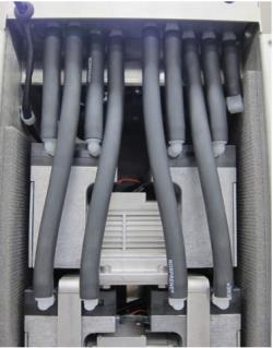
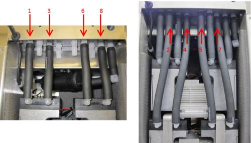
- Remove all eight black tubes from both pumps (the black tube connected to the muffler can remain connected). USE EXTREME CAUTION when removing the tubes, as the plastic connectors break easily. Label the tubes 1-8 (with tape and sharpie) so they can be re-connected later at the correct location.
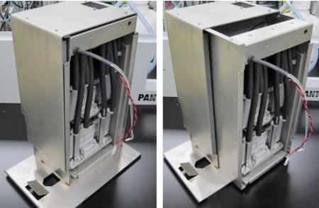
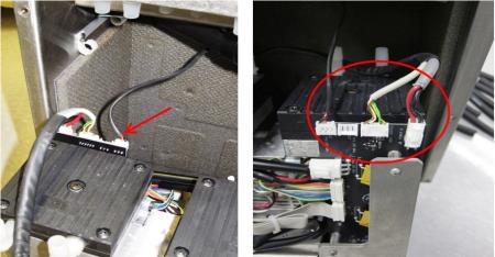
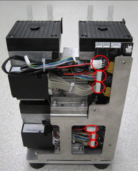
- Tilt the pump assembly out, and disconnect both power cables and the fan cable from the PCB. (The image below shows a view of the connections from behind.)

Caution—Connector crimps are fragile. Do not allow tension on the cables! - Remove the pump assembly from the inner housing by sliding it completely out.
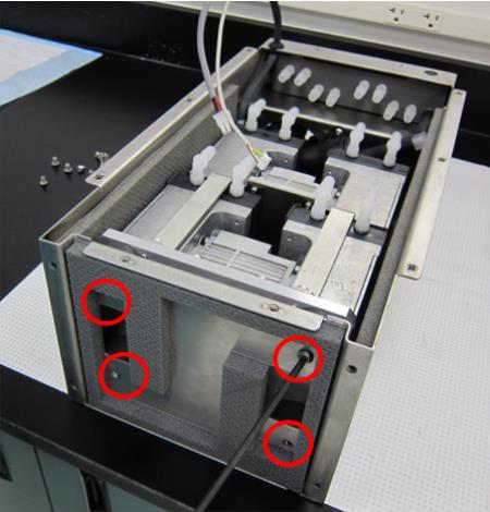
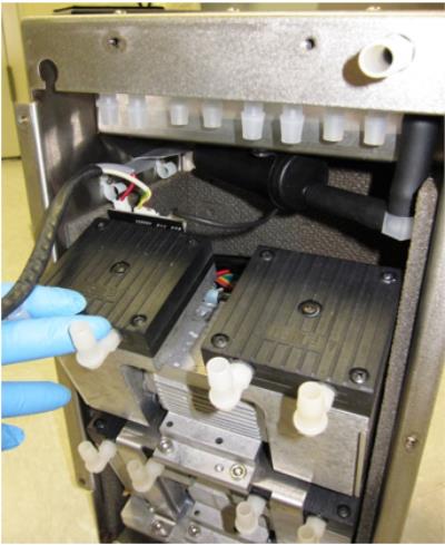
- Turn the pump assembly to view the side with the PCB. Disconnect only the three connections circled in red for the top pump. The bottom pump does not have to be removed or disconnected for a PCB replacement.
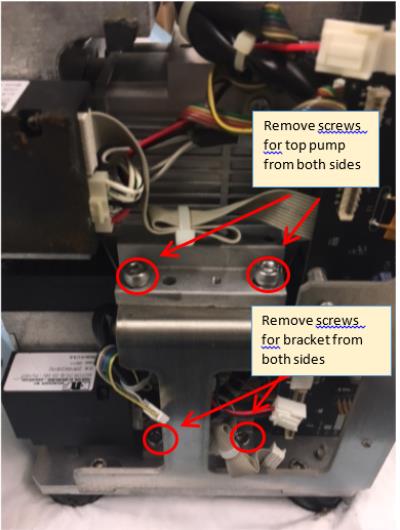
- Remove the four M6x14 screws (two on each side) that secure the top dual-head pump and take it off the pump bracket. Then remove the four M6x14 screws (two on each side) that hold the pump bracket to the bottom plate and remove the pump bracket.
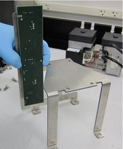
- Remove the three nuts on the back of the PCB then remove. Add Loctite to the three threaded standoffs and install the new PCB on the bracket.
Replacement Procedure
- Reverse the Removal Procedure.
- Re-install the vacuum module.
 button at the top of the page to send feedback, comments, or change requests.