Upgrade to Vacuum Module (Configuration 3) Quad-Head Pump for Serial #00281 and Above
This procedure is to be used on Panthers serial # 281 and higher. If the Panther System is serial # 280 and below, complete Upgrade to Vacuum Module (Configuration 3) Quad-Head Pump for Serial #00280 and Below
Parts and Materials Required
- Panther Tool Kit
- Vacuum Module (Quad-Head)
- Pump, Quad, Vacuum System
- Vacuum, Power Cable with Fuse and Ferrite
- PCB, Vacuum System, Quad
- Fan, Vacuum System, Quad
- Assy, Vacuum, Muffler
- Vacuum System Quad Pump, Signal Cable
Time Required
- 1 Hour and 30 Minutes
Procedure
- Put on proper PPE.
- Prepare a clean and flat work space covered with bench pads.
- Power down the Panther System and PC.
- Remove the existing vacuum module.
- Uncrate the new Vacuum Module (Quad-Head).
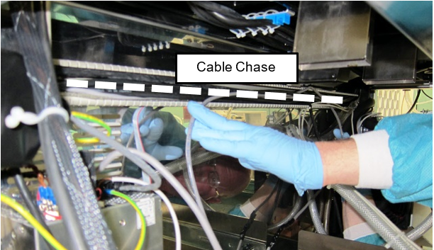
- Pull out the Mid-Bay Drawer and Waste Drawer to access the cable chase across the back of the lower bay.
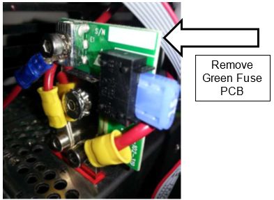
 Disconnect the old power cable (and if present the Green Fuse PCB) from the 24V power supply.

Note—Remember the location of the old vacuum ground wire. The new ground wire will attach to the power supply using the same post, located behind the new PCB.
Note—If helps to loosen and unmount the power supply from the chassis to access the screws that secure the PCB to the terminals.
Note—The Green Fuse PCB will not be reused.
- Take off the cable chase cover and remove the old power cable from the channel. Note the cable routing. Discard the old cable.
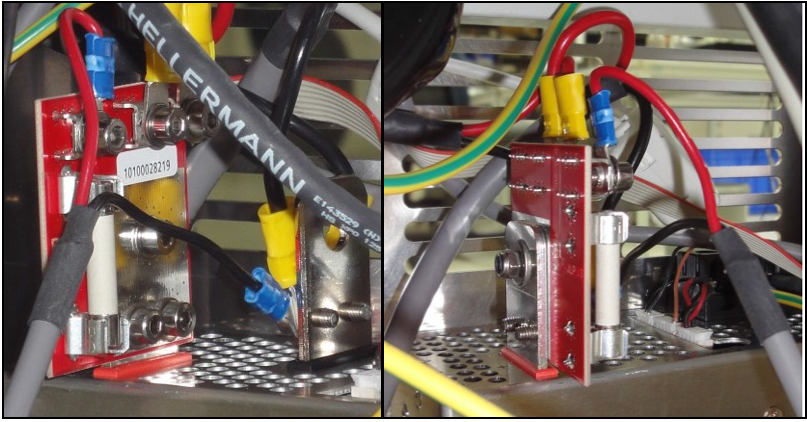
- Secure the new power cable/Red PCB onto the 24V power supply. Two screws at the bottom and a nut in the middle (included) secure the PCB to the post.
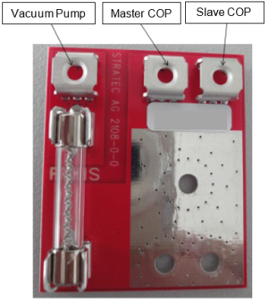
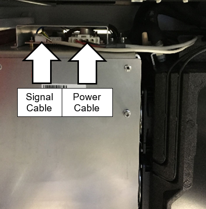
- Install the power connections to the PCB.
Note—Use the image below as a reference for power connections. - Secure the ground wire to the ground post along with the existing COP ground wire.
- Run the new power cable across the back of the cable chase to the vacuum housing.
Note—Use the same route as the previous power cable. - Reinstall the cable chase cover.
- Slide the new Vacuum Module into the system.
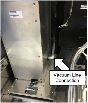
- Connect the vacuum line to the fitting on the bottom of the new module when there is enough slack.
Note—Use vacuum grease if the vacuum line is difficult to connect. - Connect the new power cable to the PCB on top of the vacuum housing.
- Plug the new signal cable into the Cooling Module PCB.
Note—If the in-line fuse cable is installed, remove and scrap the cable. - Plug the other end of the signal cable into the Red PCB on top of the vacuum housing.
- Slide the module into the system and latch in place.
Note—Check to make sure no hoses are pinched (Cooling Module and Vacuum) and cables are not interfering - Discard/Scrap old pump configuration parts as per 19-06-01-SOP Service Parts Return Procedure.
Summary listed below:
Non-repairable pumps can be scrapped on site if permitted by local requirements. If parts cannot be scrapped locally for any reason, they can by returned to Hologic for proper disposal. Contact Service Logistics for third party logistics providers that may be able to assist with disposal and recycling services.
- Procedure to the Verification section.
Verification
- Power on the Panther System and PC.
- Login to the FSE shield.
- Open Service Software.
- Initialize the Vacuum.
- Activate the Vacuum & Read the Vacuum.
- Verify the vacuum is within specifications.
The vacuum level must read between -203mbar and -270mbar and the vacuum pump speed must read above 1650rpm.
If needed refer to Configuring the Quad Head Vacuum Pump Speed. - Exit Service Software.
- Start Panther Main.
- Check Vacuum in Panther Main.
- PrimeOperation of pumping fluid through tubing to ensure proper and consistent fluid delivery (remove air from the tubing, etc.). the system
- Verify the Vacuum is within Specification
- Maintains a vacuum level between 6inHg and 8inHg.
- Verify that exhaust is flowing through the rear vent (Serial # 00281 and higher) or through the routed tubing (Serial # 00280 and lower).
- Shutdown and restart the Panther System and PC in Customer Mode and return to customer.
 button at the top of the page to send feedback, comments, or change requests.