Parts and Materials Required
- Panther Tool Kit
- VACUUM PUMP, MODULE
Time Required
- 30 minutes
Removal Procedure
- Put on proper PPE.
- Power down the Panther System.
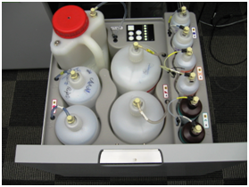
 Open the Universal Fluid Drawer.
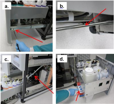
Note—It is not necessary to remove or disconnect all the fluid bottles to perform the procedure. Note—It is also not necessary to remove the front cover of the Universal Fluid Drawer. If left in place, find a box or similar object to provide some support when the drawer is removed from the rails. - Remove the Universal Fluids Drawer as shown below:
- Free the drawer from the slides in the front (left side and right side) by twisting each front tab up with a flathead screwdriver.
- Supporting the drawer, push the slides back. Then pull drawer forward to unhook from back horizontal tabs.
- Turn the drawer to the side and move out of the way. Do not stretch or strain any tubing.
- Set the drawer on an appropriately-sized supporting object. (If front cover was removed, the drawer can sit flat on the floor.
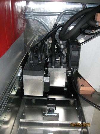
- Locate the vacuum pump module in the Lower Bay.
- Flip up the latch on the front of the module and unhook it from the floor of the system.
- Slide the module forward as far as the cables and tubing will allow.
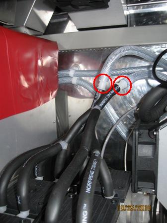
- Disconnect the two black vacuum tubes from barbed connections to braided, clear tubing. (Label if necessary, one black tube comes from the Waste Drawer and one goes to the muffler.)
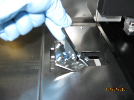
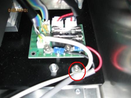
- Locate the PCB on the back left corner of the base of the vacuum module. (The PCB may also be found on the front right corner of the base.)
- Using a 3 mm hex drive, remove the cable clamp.
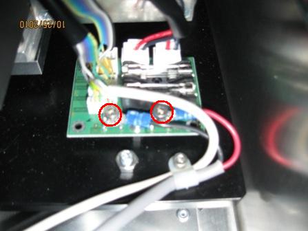
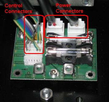
- Using a 3 mm hex drive, disconnect both power cable connections from the PCB.
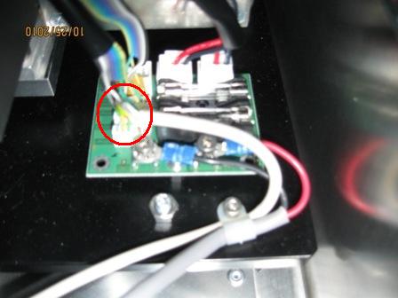
- Disconnect the control cable from the PCB.
- Slide the vacuum module out of the system and place on a clean work area.
Replacement Procedure
- Prior to installing the pump module, connect the pump power connectors and control connectors to the PCB on pump module base as shown.
- Reverse the removal procedure.
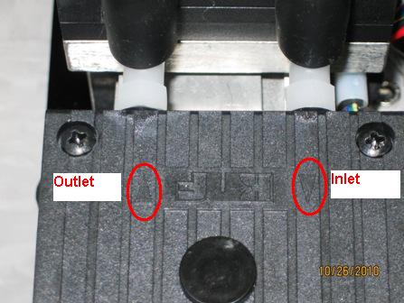
Note—When connecting vacuum tubing, make sure that the exhaust tubing (to muffler) is connected to the exhaust side of the pump heads and the inlet tubing (to manifold) is connected to the inlet side of the pump heads. Pump head inlet and outlet are marked as shown in the picture below.
 button at the top of the page to send feedback, comments, or change requests.