Parts and Materials Required
- Socket or nut driver, 7 mm
- Heat sink compound
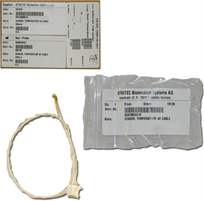
 SAMPLE/REAGENT BAY, TEMP SENSOR
Time Required
- 30 minutes
Removal Procedure
|
|
Wear clean nitrile gloves while performing the following procedures. |
- Remove the Sample Bay module.
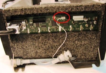
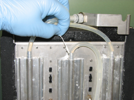
- Disconnect the thermistor connector from the PCB on the rear of the module.
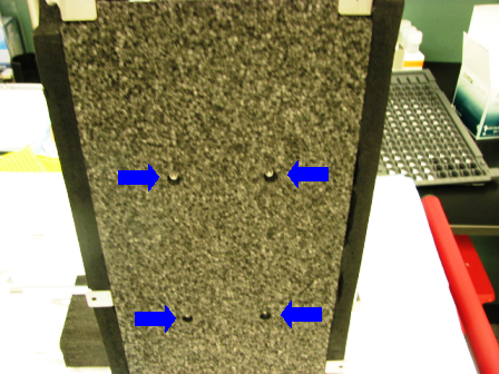
- Using a 7 mm socket or nut driver, remove the four 4 mm nuts and washers that secure the solid foam insulation to the bottom of the module. The soft foam rubber on the sides of the module is attached with double stick tape and may make it difficult to remove the foam from the bottom. Peel the sticky foam back where it is attached to the bottom foam.
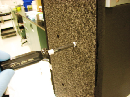
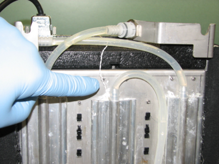
- Follow the thermistor wires to locate the thermistor where it is inserted into the cooling fin. Gently pull the thermistor out of the cooling fin.
Replacement Procedure
- Insert the new thermistor in the cooling fin. It may be necessary to coat the thermistor with heat sink compound to assure proper thermal contact with the cooling fin.
- Route the thermistor wires to the rear of the module and connect to the printed circuit board.
- Carefully replace the solid foam insulation on the module. Be sure that the liquid cooling lines are properly inserted in the channels provided or the foam will not sit flush.
- Press the black, sticky backed foam rubber insulation back onto the edges of the solid foam.
- Replace the four 4 mm washers and nuts. Tighten just tight enough to retain the foam but not so tight as to rip through the insulation.
Alignment/Calibration
Verification
- Start up Service Software.
- Using Service Software, verify that the Sample Bay temperature is within acceptable range.
- Scan racks with tubes of all eight lanes.
- Verify the detection of rack presence.
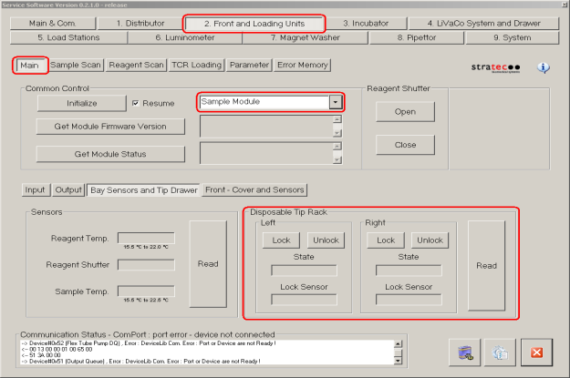
- Using Service Software, initialize the sample module and verify the Tip Drawers Sensors. Check the sensors are properly wired and work correctly. Use the Read button to verify the State of the drawer is correct by opening and closing the drawers individually.
- Verify Tip Drawers lock and unlock. With the left drawer in, lock the drawer. Verify the Lock Sensor reads locked using the Read button. Unlock the drawer and verify the Lock Sensor reads unlocked using the Read button. Do the same with the right drawer.
 button at the top of the page to send feedback, comments, or change requests.