Parts and Materials Required
- Hex driver, 2.5 mm
- SAMPLE BAY, PCB
Time Required
- 30 minutes
Removal Procedure
|
|
Wear clean nitrile gloves while performing the following procedures. |
- Remove the Sample Bay module.
- Place the module on appropriate pads to reduce the possibility of contamination.
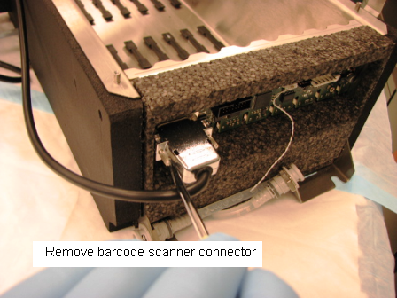
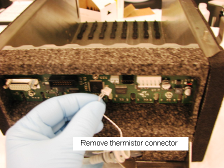
 Disconnect the thermistor and barcode scanner connectors from the PCB.
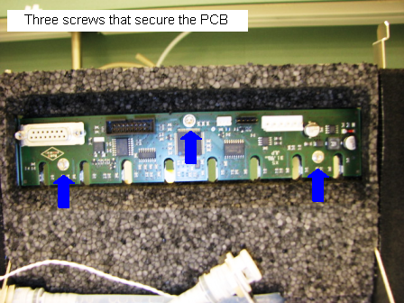
- Using a 2.5 mm hex driver, remove the three 3 mm socket head cap screws that secure the PCB to the module.
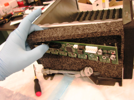
- Pull the foam away from the module to allow the PCB to be wiggled free and removed.
Replacement Procedure
- Reverse the removal procedure.
- Replace the Sample Bay module.
Firmware and Teaching
Verification
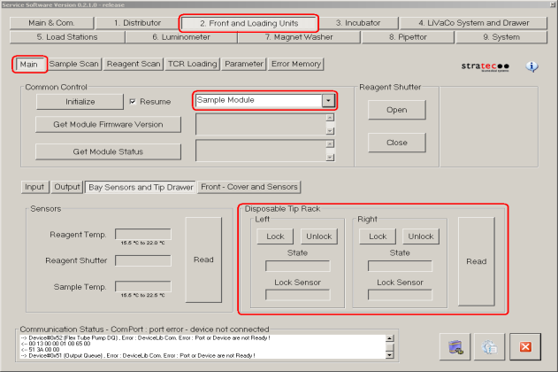
- Start up Service Software.
- Using Service Software, verify that the Sample Bay temperature is within acceptable range.
- Scan racks with tubes of all eight lanes.
- Verify the detection of rack presence.
- Using Service Software, initialize the sample module and verify the Tip Drawers Sensors. Check the sensors are properly wired and work correctly. Use the Read button to verify the State of the drawer is correct by opening and closing the drawers individually.
- Verify Tip Drawers lock and unlock. With the left drawer in, lock the drawer. Verify the Lock Sensor reads locked using the Read button. Unlock the drawer and verify the Lock Sensor reads unlocked using the Read button. Do the same with the right drawer.
 button at the top of the page to send feedback, comments, or change requests.
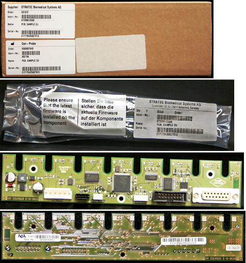