Peristaltic Pump Tubing Removal and Replacement

Parts and Materials Required

  • Proper PPE
  • Minimum of 4 MTUs
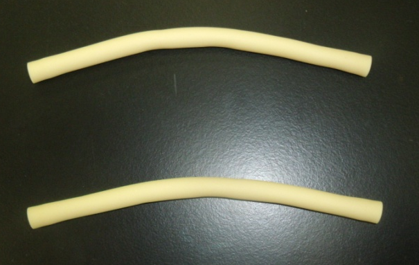
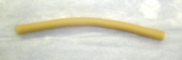
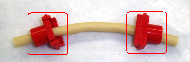
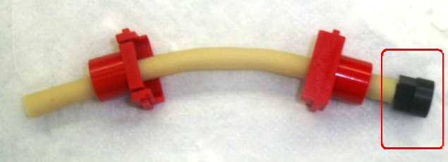
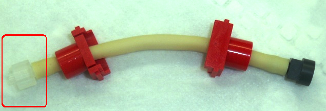
  • PANTHER PERISTALTIC TUBING, NO FITTINGS

    or

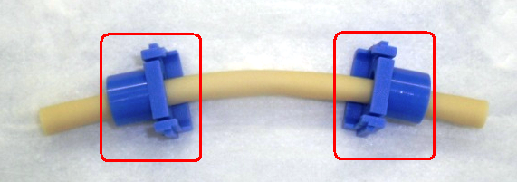
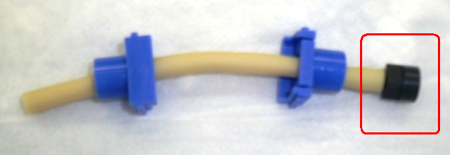
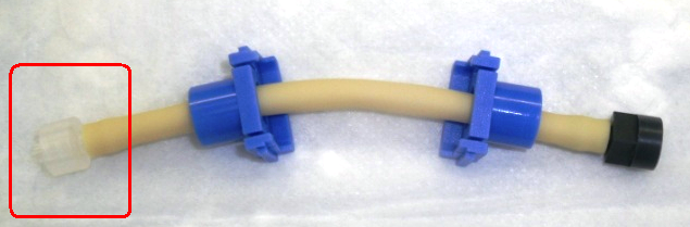
  • PANTHER PERISTALTIC TUBING KIT, WITH FITTINGS

Time Required

  • 30 minutes

Preparation

Initialize Modules

  1. Put on proper PPE.
  2. Start up Service Software.
  3. Initialize the Distributor.
    1. In Service Software, select Distributor > Main.
    2. Highlight Distributor and press Initialize.
  4. Initialize the MTUClosedMulti-tube unit—Container used to process tests in the instrument. An MTU contains five separate reaction tubes. The MTU is moved through the instrument by the linear distributor and includes five tiplets for pipettiing to be used in the mag wash station. Input Queue.
    1. In the service software, select Front and Loading Units > Main.
    2. Highlight MTU Input Queue and press Initialize.
  5. Initialize the Output Queue.
    1. In the service software, select Front and Loading Units > Main.
    2. Highlight Output Queue and press Initialize.

Load MTUs

  1. Open the MTU Input Queue drawer and load at least 4 MTUs.
  2. Close the MTU Input Queue drawer.
  3. Push the MTUs.
    1. In the service software, select Front and Loading Units > Main > Input > Sensors & Actors.
    2. Press Push MTU.
  4. Insert an MTU into the Output Queue in order to catch any deactivation fluid that might drip during the replacement of the peristaltic pump tubing.
    1. In Service Software, select Distributor > Move Distributor > Single Movement to.
    2. Double-click MTU Input Queue to grab an MTU.
    3. In Service Software, select Distributor > Move > Single Movement to.
    4. Double-click Output Queue to place an MTU.
      WARNING—Check the Output Queue to confirm that an MTU was actually inserted into the module.
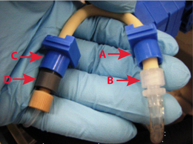
      Note—Replace according to the two types of parts: (A) PERISTALTIC TUBING, NO FITTINGS, AND (B) PERISTALTIC TUBING KIT, WITH FITTINGS.

ClosedPeristaltic Tubing, No Fittings, Procedure

Remove the Peristaltic Pump Tubing Assembly

  1. ClosedLocate the peristaltic pump.

    Each pump has two peristaltic pump tubing assemblies (fluid pathways). Begin with the rear peristaltic pump tubing assembly.

  2. ClosedPress on both release points on the rear peristaltic pump housing top cover and pull upward to remove the cover.
  3. Wait 15 seconds to allow fluid to drain back to the service bottle.
  4. ClosedSlide each end of the peristaltic pump tubing assembly away from the pump to remove the assembly.
  5. ClosedRemove the fittings and connectors (A–D) on both ends of the peristaltic pump tubing assembly and retain these connectors.
  6. Discard the old peristaltic pump tubing (just the beige two tubings) in the biohazard waste.
    Note—If the module will be returned, clean the module.
  7. Change gloves.

Replace the Peristaltic Pump Tubing Assembly, No Fittings

  1. ClosedLocate the new peristaltic pump tubing assembly.
    Note—Only the beige pieces of tubing are supplied in the assembly. The ends that were removed in step 4 in the Removal section will be used to make a complete assembly.
  1. ClosedPlace one piece of the beige tubing on an absorbent pad.
  2. ClosedPlace the blue connectors on the ends of the beige tubing.
  3. ClosedConnect one connector to the right side of the tubing.
  4. ClosedConnect the second connector to the left side of the tubing.
  5. ClosedPlace the second beige tubing on an absorbent pad.
  6. ClosedPlace the red connectors on the ends of the beige tubing.
  7. ClosedConnect one connector to the right side of the tubing.
  8. ClosedConnect the second connector to the left side of the tubing.
  9. ClosedReplace the rear peristaltic pump housing top cover and ensure the tabs follow the grooves.
  10. Repeat the previous steps for the front peristaltic pump tubing assembly.
    ClosedNote—Route the tubing as showing in the following image.

Calibration

  • None

Verification

  1. PrimeClosedOperation of pumping fluid through tubing to ensure proper and consistent fluid delivery (remove air from the tubing, etc.). the system through the Panther System main software.
  2. Perform a Visual Dispense Verification to the Output Queue.

ClosedPeristaltic Tubing Kit, With Fittings, Procedure

Remove the Peristaltic Pump Tubing Assembly

  1. ClosedLocate the peristaltic pump.

    Each pump has two peristaltic pump tubing assemblies (fluid pathways). Begin with the rear peristaltic pump tubing assembly.

  2. ClosedPress on both release points on the rear peristaltic pump housing top cover and pull upward to remove the cover.
  3. Wait 15 seconds to allow fluid to drain back to the service bottle.
  4. ClosedSlide each end of the peristaltic pump tubing assembly away from the pump to remove the assembly.
  5. ClosedRemove the fittings and connectors (A–D) on both ends of the peristaltic pump tubing assembly and retain these connectors.
  6. Discard the old peristaltic pump tubing (just the beige two tubings) in the biohazard waste.
    Note—If the module will be returned, clean the module.
  7. Change gloves.

Replace the Peristaltic Pump Tubing Kit, With Fittings

  1. Locate the new peristaltic pump tubing kit assembly (the assembly includes fittings).
  2. Attach the appropriate fittings for the Output Queue injector tubing and the Output Queue deactivation fluid tubing to the new peristaltic pump tubing assembly.
  3. ClosedSlide each end of the tubing assembly into the pump.
  4. ClosedReplace the rear peristaltic pump housing top cover and ensure the tabs follow the grooves.
  5. Repeat the previous steps for the front peristaltic pump tubing assembly.
    ClosedNote—Route the tubing as showing in the following image.

Verification

  1. Prime the system through the Panther System main software.
  2. Perform a Visual Dispense Verification to the Output Queue.