Visual Dispense Verification Procedures
Scope
A Visual Dispense Verification is a quick method to check the overall dispense of fluids within a module for approximate volume and consistency verification.
A Visual Dispense Verification can be performed in the Luminometer, the Magnetic Washes, and in some cases, in the Output Queue. This procedure is to be used as a troubleshooting tool only, and is not intended to be an accurate measurement.
Parts and Materials Required
- Service Software Beta 15 or later
Time Required
- 1 hour
Procedure
Startup Sequence
- Start up the system main assay software and let the system complete the unload sequence (Reference to the Operator's Manual).
- Verify that the initialization sequence is complete and goes into the unloading of MTUs.
- Prime
 Operation of pumping fluid through tubing to ensure proper and consistent fluid delivery (remove air from the tubing, etc.). the system (see the Panther System Operator's Manual).
Output Queue Visual Dispense Verification
- Verify that MTUs are present and perform a system prime (Reference to the Operator's Manual).
- During the prime sequence, for the first MTUs, monitor the bleach and buffer lines to confirm that no leaks are present at the connections, pumps, and/or valves.
- Monitor the Output Queue as it dispenses fluid into the tube. Confirm each tube is receiving the same amount of fluid and that the module is placing the MTUs onto its stack properly and consistently.
Magnetic Wash Module Visual Dispense Verification
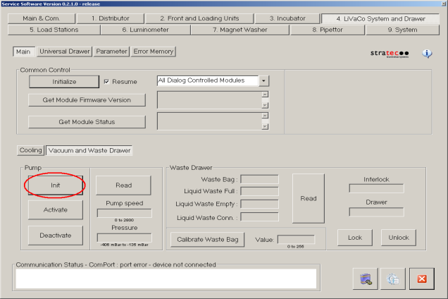
- Start up Service Software.
- Ensure that the vacuum system is Initialized and Activated.
- Ensure that the Mag Wash(es) are primed. If any fluid fittings have been loosened it will be necessary to prime. To prime a Mag Wash:
- Navigate to the Distributor tab and insert a new MTUMulti-tube unit—Container used to process tests in the instrument. An MTU contains five separate reaction tubes. The MTU is moved through the instrument by the linear distributor and includes five tiplets for pipettiing to be used in the mag wash station. into the Magnetic Wash module.
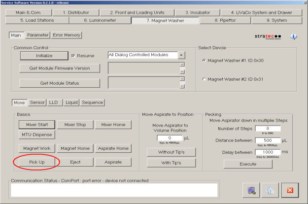
- Pick tiplets from the MTU. Under the Move tab, select Pick Up to pick the tiplets.
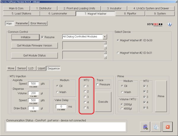
- Navigate to the Sequence section under 7 Magnet Washer tab in Service Software, inject 2000 µL of wash buffer. Make sure to check all 5 tubes of the MTU. Be sure that you have selects the appropriate Mag Wash device (#1 or #2).
- Confirm that the system is primed by checking for air bubbles in the lines. If the system is still not primed Aspirate the fluid from the MTU tube by pressing Aspirate. Then repeat steps a–d. Repeat these steps for oil if necessary and/or for the other Mag Wash.
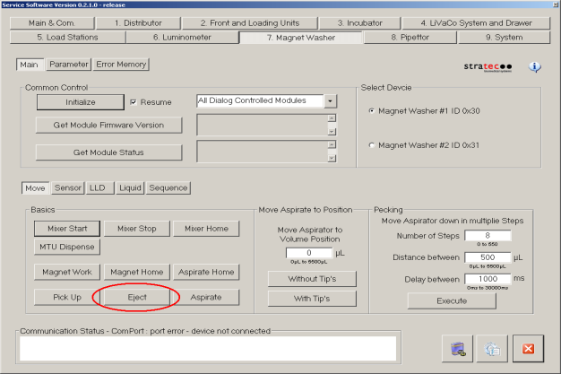
- Use the linear distributor to remove the MTU from the Mag Wash. Eject the tiplets from the Mag Washes that have been primed by pressing Eject.
- Navigate to the Distributor tab and insert a new MTU into the Magnetic Wash module.
- In the Sequence section under 7 Magnet Washer tab in Service Software, inject 2000 µL of wash buffer, followed by 2000 µL of oil. Make sure to check all 5 tubes of the MTU. Be sure that you have selected the appropriate Mag Wash device (#1 or #2).
- Navigate the Distributor to place the MTU into the service queue for inspection.
- Inspect the MTU.
- The overall fluid level should be visually consistent across each tube.
- The dividing line between wash and oil should be noticeable and consistent across each tube.
- Air bubbles and foam in the liquid should be minimal.
- Using the service queue and the Distributor, place the filled MTU back into the Magnetic Wash module.
- Under the Move tab, select Pick Up to pick the tiplets.
- Confirm the vacuum is still active and select Aspirate.
- Once again, move the MTU to the service queue and inspect it to confirm the tiplets are missing and all the fluid has been aspirated from each tube.
- Dispose of the MTU and repeat the procedure with Magnetic Wash 2.
Luminometer Module Visual Dispense Verification
- Start up Service Software.
- Navigate to the 6. Luminometer tab.
- Confirm that the Luminometer contains no MTUs.
- Click Emergency Unload/Grab of the second MTU and follow the prompts.
- Use the Distributor to remove any MTUs left in the Luminometer.
- Place a new MTU in the module with the Distributor and use the Prime function under Sequence to prime the AD1 and AD2 lines to the injector.
- Check all AD1 and AD2 lines and connections and check for leaks at pumps and valves.
- Remove the MTU from the Luminometer to the service queue.
- Inspect the MTU for:
- The overall fluid level should be visually consistent across each tube.
- Air bubbles and foam in the liquid should be minimal.
- Start up the Panther System software and verify that once the system is in a steady state, the vacuum pressure reads between 6 and 7.
 button at the top of the page to send feedback, comments, or change requests.