Parts and Materials Required
- Hex wrench, 2.5 mm
- Hex wrench, 3 mm
- MAGWASH, INJECTOR
Time Required
- 1–2 hours
Removal Procedure
- Put on proper PPE.
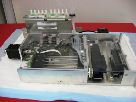
- Remove the Magnetic Wash module.

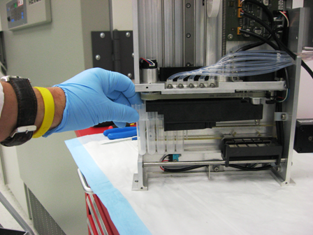
Wear clean nitrile gloves while performing the following procedures.  Place the Magnetic Wash module on a properly protected work surface.
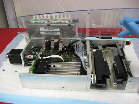
- Using a 2.5 mm hex wrench, remove the seven 3 mm screws that secure the clear module cover and lift the cover off the module.
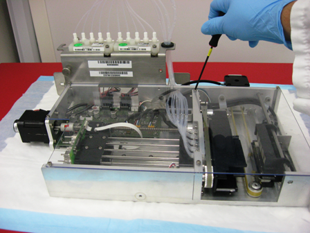
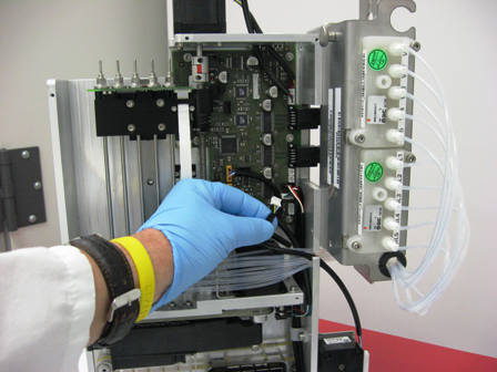
- Disconnect the magnet motor cable from the main PCB.
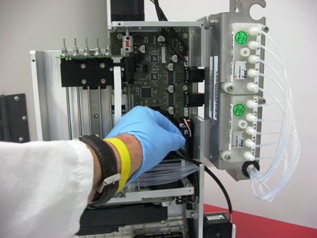
- Rotate the module and stand it in an upright position. Insert an MTUMulti-tube unit—Container used to process tests in the instrument. An MTU contains five separate reaction tubes. The MTU is moved through the instrument by the linear distributor and includes five tiplets for pipettiing to be used in the mag wash station. into the module and position it under the injectors to capture any fluid that is retained in the injector line.
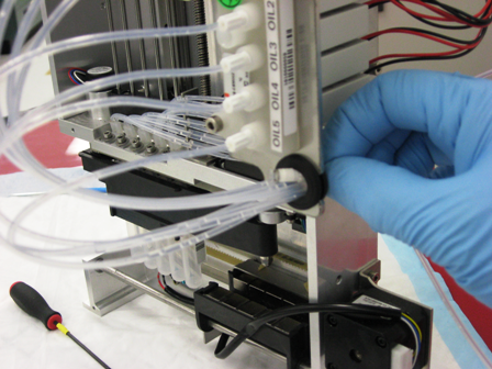
- Disconnect the desired injector lines from both the wash and the oil valve blocks.
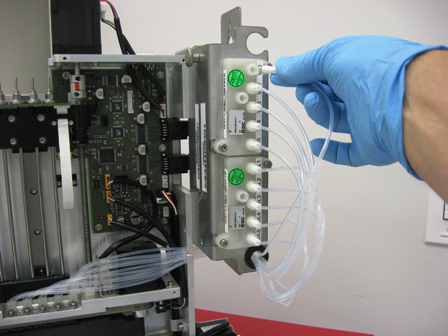
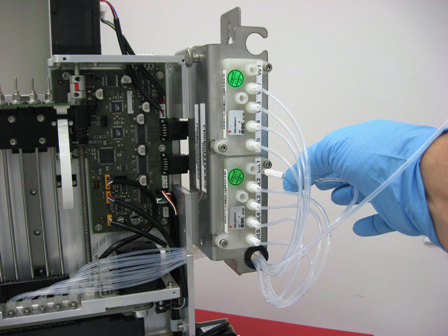
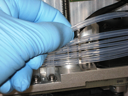
- Free the injector lines from the grommet and free them from the retainers mounted to the frame.
- Using a 3 mm hex wrench, remove the screw that secures the injector and remove the injector.
- If replacing more than one injector, it is recommended that each injector be removed and replaced one at a time in order to avoid connecting the tubing to the incorrect port.
Replacement Procedure
- Insert the new injector.
- Install the 3 mm screw and washer, and tighten. Be sure that the injector is angled to properly inject wash and oil into the MTU. Use the other injectors as a guide to proper orientation.
- Route the lines neatly through the original mounting brackets, through the rubber grommet, and to the wash and oil valve blocks.
- Connect the new injector lines to the valve blocks so that the nozzle toward the front of the module is connected to the wash valve block and the nozzle to the rear of the module is connected to the oil valve block.
- Re-install the clear cover and its seven screws.
- Install the Magnetic Wash module.
- Check for leaks at all fittings.
Alignment/Calibration
Verification
- Perform a Visual Dispense Verification Procedure.
- Perform the Magnetic Wash Dispense and Process Control Verification procedure.
- Perform a System Level Operational Qualification.
- PrimeOperation of pumping fluid through tubing to ensure proper and consistent fluid delivery (remove air from the tubing, etc.). the system(see the Panther System Operator's Manual).
 button at the top of the page to send feedback, comments, or change requests.
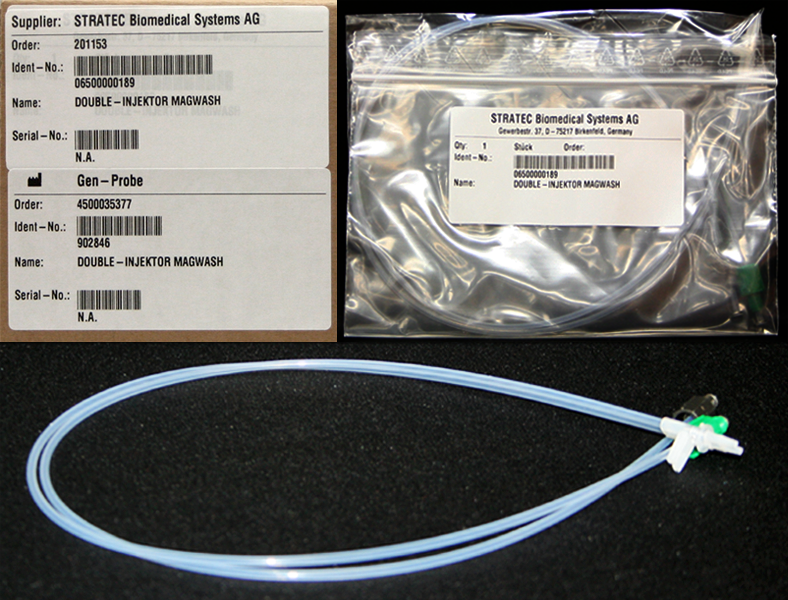