Parts and Materials Required
- Allen wrench, 2.5 mm
- COOLING MODULE, PCB
Time Required
- 10 minutes
Removal Procedure
- Put on proper PPE.
- Power down the system.
- Open the right side panel door.
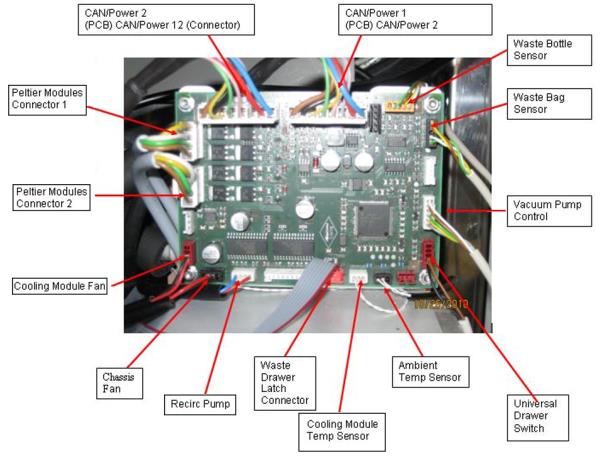
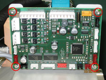
- Remove the PCB.
Replacement Procedure
- Power on the Panther system.
- Close the right side panel door.
- Install Panther System firmware.
Verification
- Verify the temperatures of the Sample Bay and Reagent Bay.
- Verify vacuum pressure.
- Verify that the Universal Fluid Drawer opens, closes, locks, and unlocks.
- Verify that the Waste Drawer opens, closes, locks, and unlocks.
- Verify that the waste bag presence sensor operates.
- Verify Liquid Waste Bottle level sensing.
- Verify that the right-side Panther System cooling fan functions properly.
 button at the top of the page to send feedback, comments, or change requests.
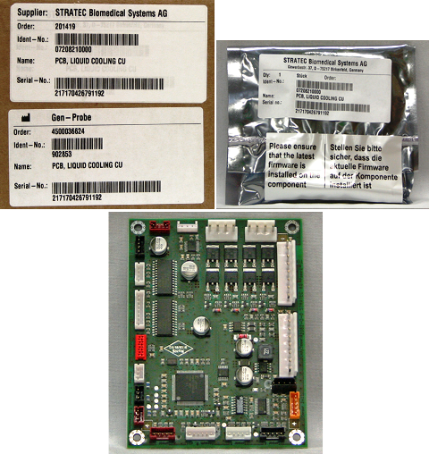