Cooling Module Temperature Sensor Removal and Replacement (Dual Fan)
Parts and Materials Required
- Open-ended wrench, 8 mm
- High Temp Thermal Grease
- COOLING MODULE, TEMPERATURE SENSOR
Time Required
Removal Procedure
- Put on proper PPE.
- Remove the Cooling Module from the system.
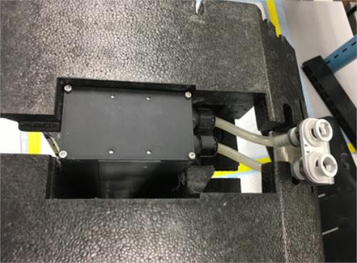
 Unplug the Recirculation Pump inlet tubing from the cooling module.
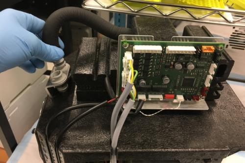
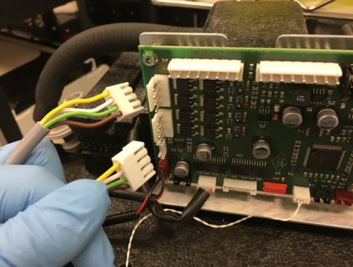
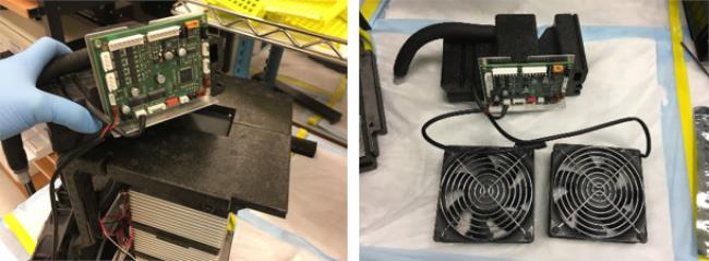
- Unplug the Peltier wire connectors from the PCB. Label the cables (for re-connection).
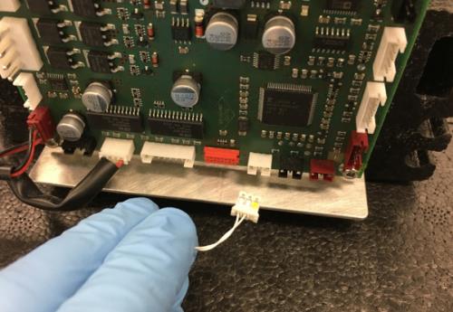
- Unplug the Cooling Module Temperature Sensor from the PCB.
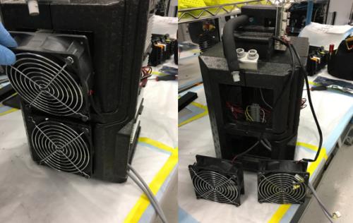
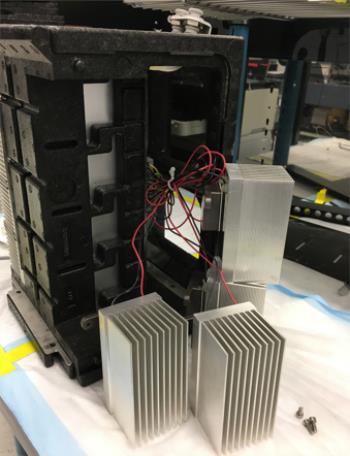
- Remove the Dual Fans from the Cooling Module foam casing and set on the bench.
- Remove the foam mounting block that holds the Cooling Module PCB and Cooling Pump. Set the block aside.
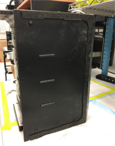
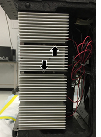
- Remove the black plastic panel from the side of the cooling module to access the four Peltiers on the right (if facing the Peltiers).
- Remove all four Peltiers from the right side of the Cooling Module (with respect to the fill tube):
- Remove all four stabilizing screws first.
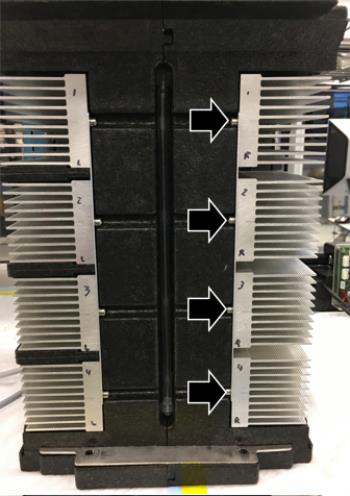
- Remove the three foam inserts between the Peltiers.
- Remove the eight Peltier mounting screws. There are two on each module, one on the upper right and one on the lower left.
- It is not necessary to unplug each Peltier wire. Set the Peltiers on a clean bench pad outside the Cooling Module.
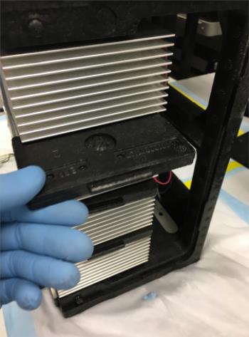
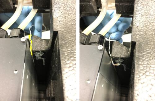
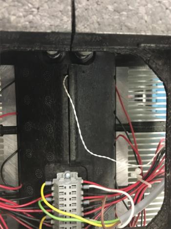
- Separate the right half of the Cooling Module foam casing from the left. The Temperature Sensor is housed in the right half of the foam case.
- Remove the Temperature Sensor. Note the location of the rubber grommet on the old sensor wire.
Replacement Procedure
- Completely coat the Cooling Module Temperature Sensor with thermal grease.
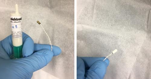
- Place the end of the sensor in its slot and route the cable through the foam cable guide, in the same manner as the old sensor. Install the rubber grommet in the same manner as before.
- Reconnect the two halves of the foam casing, making sure that the temperature sensor remains in its slot and makes contact with the outside of the Cooling Module reservoir.
- Reinstall the four Peltiers.
- Reinstall the three foam inserts that go between the Peltiers.
- Replace the black plastic panel.
- Place the black foam PCB/Pump housing block on top of the cooling module.
- Reinstall the Dual Fans.
- Plug the inlet tubing from the pump back into the Cooling Module.
- Plug the two Peltier wire connectors back into the PCB.
- Route the two Peltier wires and the Temperature Sensor wire through their cable guide.
- Plug the Temperature Sensor into the Cooling Module PCB.
- Reinstall the Cooling Module.
Verification
- Verify the temperatures of the Sample Bay and Reagent Bay.
- Visually inspect the fluid height within the Cooling Module.
- Verify vacuum pressure.
- Verify that the Universal Fluid Drawer opens, closes, locks, and unlocks.
- Verify that the Waste Drawer opens, closes, locks, and unlocks.
- Verify that the waste bag presence sensor operates.
- Verify Liquid Waste Bottle level sensing.
- Verify that the right-side Panther System cooling fan functions properly.
Click the  button at the top of the page to send feedback, comments, or change requests.