Universal Fluids on the Fly Module Installation
Parts and Materials Required
- Panther Tool Kit
- Sharpie
- Continuous Access Parts Kit
Procedure
 Unpack the Universal Fluids on the Fly Module
- Unpack the Bleach Bottle.
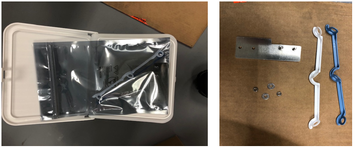
Remove the bag containing the tubing separators and the waste bottle sensor bracket from the waste bottle.
Ensure all components are included as shown.
Tubing Separators (blue and white), Bleach Sensor relocation bracket nuts and spacers.
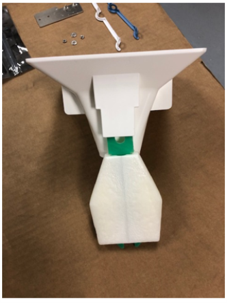
- Remove foam from the float in the waste bottle.
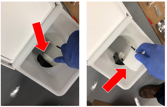
- Install the float onto the waste bottle insert. Make sure float is correctly oriented as shown.
- Place an absorbent pad below the Universal Fluids Drawer.
 | Caution—Fluid leaks are possible in this procedure. |
- Remove the Universal Fluid drawer front panel.
 | Note—Save screws for reassembly. |
- Remove all fluid bottles from the UFD Drawer.
- Push the Wash, Deactivation, and Bleach fluid lines into the UFD bin.
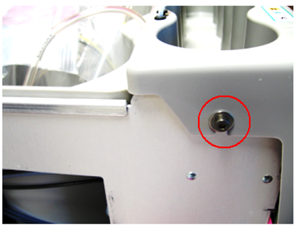
- Loosen but do NOT remove the left and right side screws of the Universal Fluids drawer tub.
 .
.
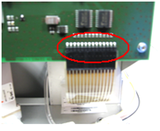
- Slightly lift the small bin cover to access the Universal Fluid Drawer PCB.
- Disconnect the RFID cable from the right side of the Universal Fluid Drawer PCB.
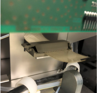
- Open the cable guide, (if present).
- Shift the small bin so that you can lift the large bin out of the drawer.
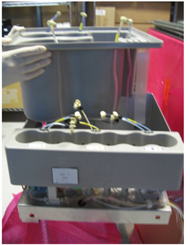
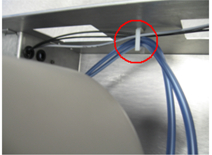
- Release the blue tubing so that the bin can be lifted farther out of the drawer.
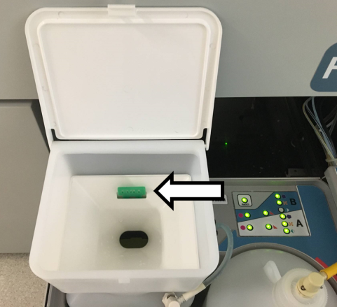
- Locate the Bleach Sensor on the side wall of the UFD.
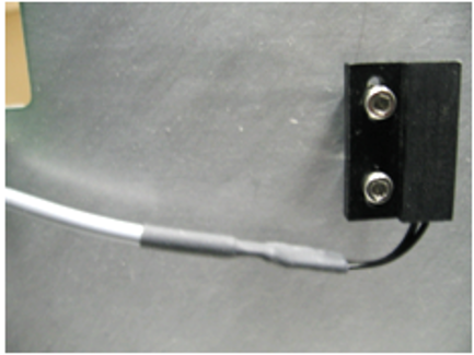
- Remove the two screws that secure the sensor to the UFD sidewall with a 2.5mm Allen wrench. Save the screws for reassembly.
- Remove the nuts and washers from the two screws that are fixed to the adapter plate.
- Secure the Bleach Sensor onto the adapter plate as shown below, using the two nuts and washers.
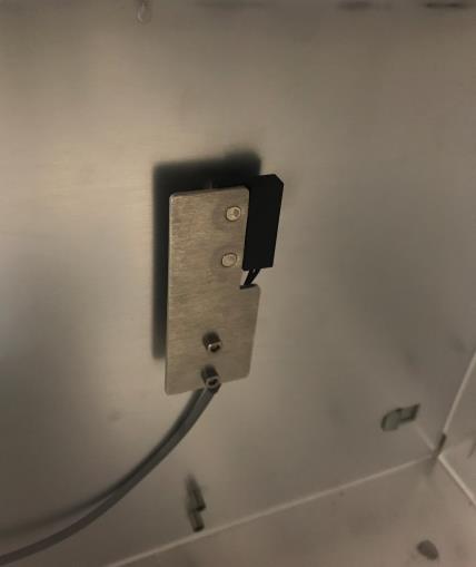
- Use the two 2.5mm screws removed earlier to attach the adapter plate/sensor assembly to the sidewall of the UFD.
- Place the large bin back into the UFD Drawer.
- Reconnect the RFID cable.
- Remove the large O-ring (between the two smaller O-rings) in the top panel of the tub between fluid lines for AD1, AD2, and Oil.
- Remove the bottle fittings AND tubing separators from all tubing.
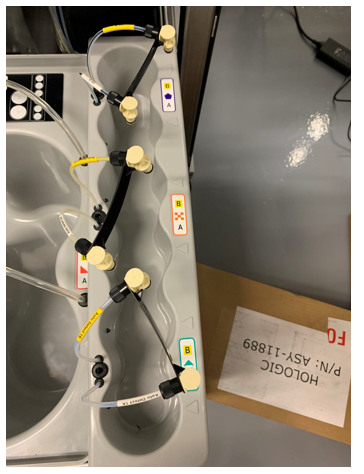
- Install the new tubing separators and re-install Oil B and AD1A fittings.
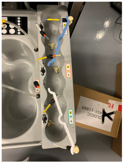
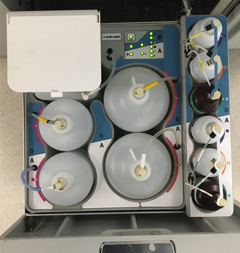
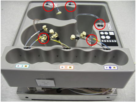
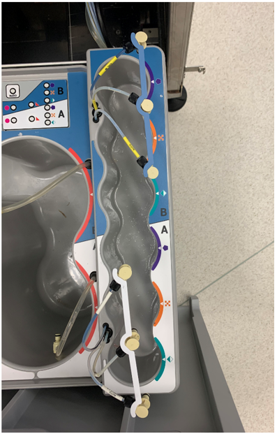
- One at a time remove the AD1B, AD2A & B, and Oil A lines and reroute per the picture below.
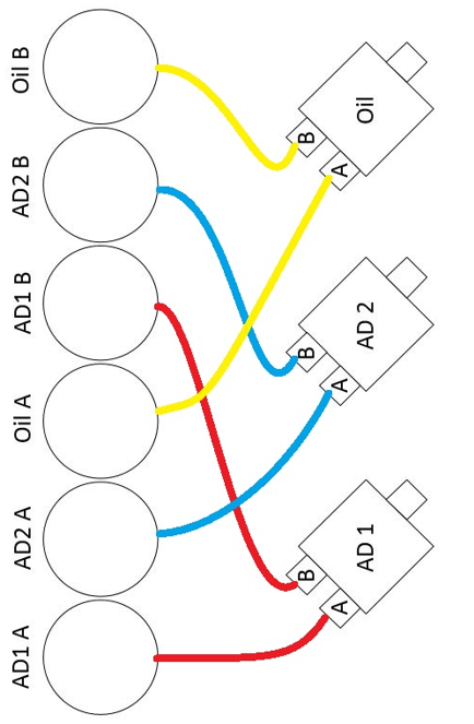
- Route all of the fluid lines through the tubing separators and install the fittings and ferrules.
Replace ferrules as needed.
- Tighten the screws securing the small bin to the UFD Drawer.
- Clean the top surfaces of both Universal Fluid drawer tubs with isopropanol and allow to dry.
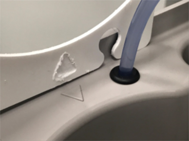
- Install the new drawer labels as shown.
|
|
Note—Ensure the triangular cutouts in the labels align with the raised triangular features on the top surface of the drawer tubs.
|
- Reinstall the Universal Fluids Drawer front panel.
- Continue to Firmware, Alignment and Teaching
Click the  button at the top of the page to send feedback, comments, or change requests.