Prepare the Panther for MTU Expansion
Procedure
- Power down the Panther System.
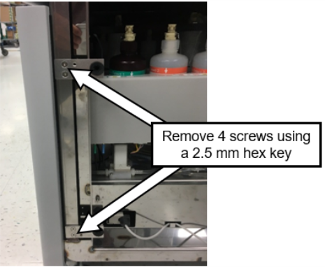
- Remove the right-side door.
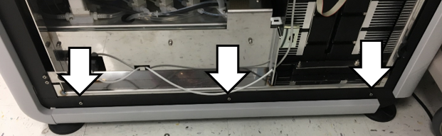
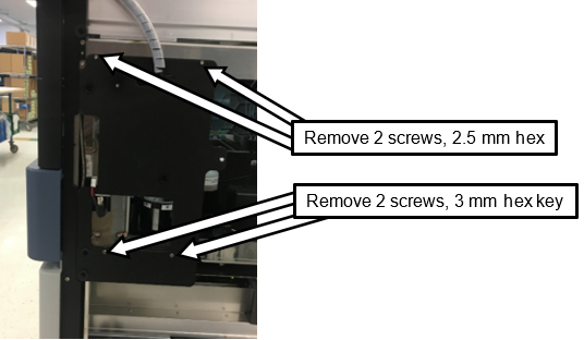
 Remove and discard the lower trim and mounting trim.
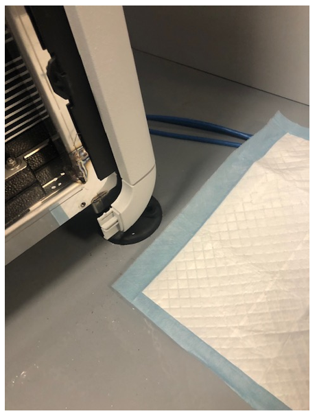
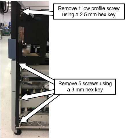
- Remove and discard the rear corner trim piece.
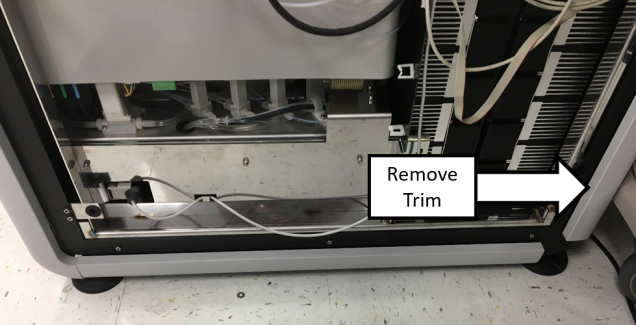
- Remove the back trim piece.
- Install the lower profile cover onto the back trim piece.
- Reinstall the back trim piece.
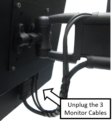
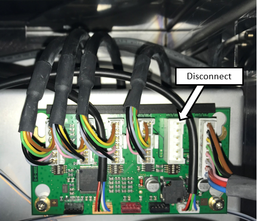
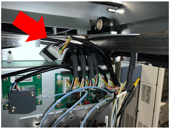
- Disconnect the cables to the PCAP monitor.
- Remove and save the cable clamps securing the monitor cables
- Route the cables away from the Monitor Arm and out of the cable channels.
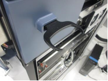
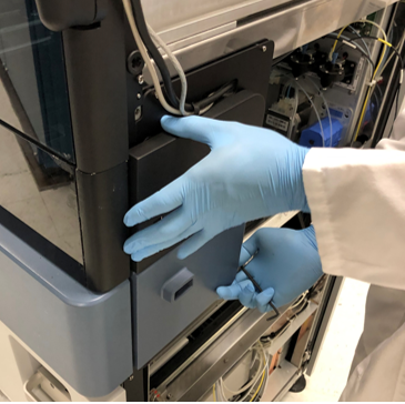
- Remove the Hand-held Scanner Bracket.
- Remove the USB Hub Expansion Cover.
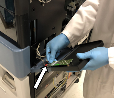
- Unplug the Power and USB cables AND discard the USB Hub Expansion Cover
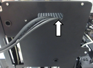
- Route the Monitor and USB Hub cables into the Panther.
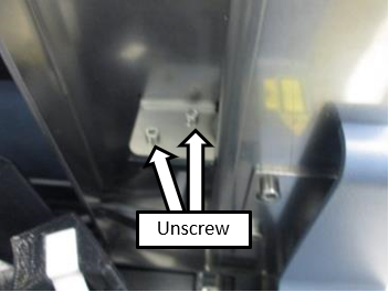
- Remove the USB Hub Expansion Cover Mounting Bracket.
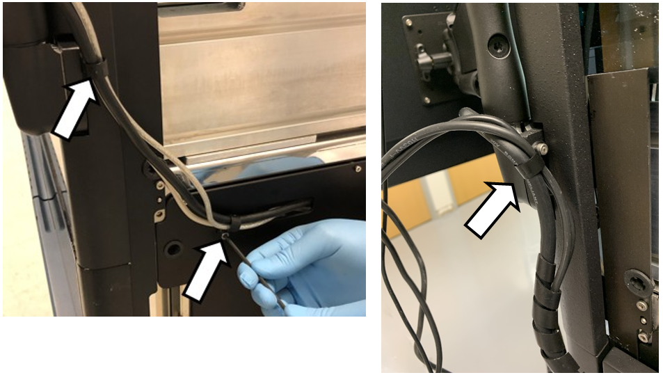
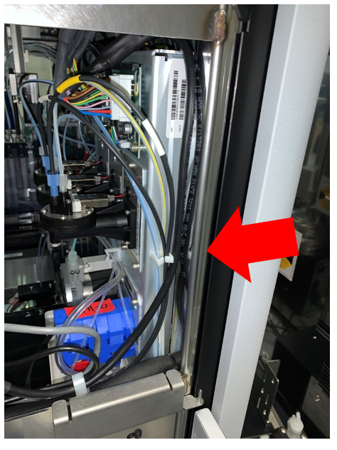
- Remove the USB Hub cables from their routing through the Chassis frame.
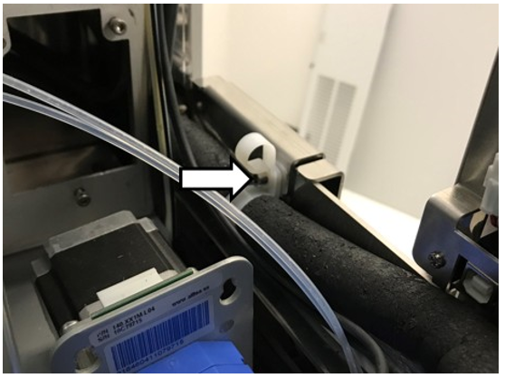
- Release the USB Hub cables from the front cable clamp.
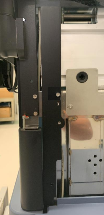
- Remove the black trim from the front right-side of the Panther.
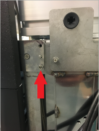
- Remove and save this screw to be used again when installing the new bracket.
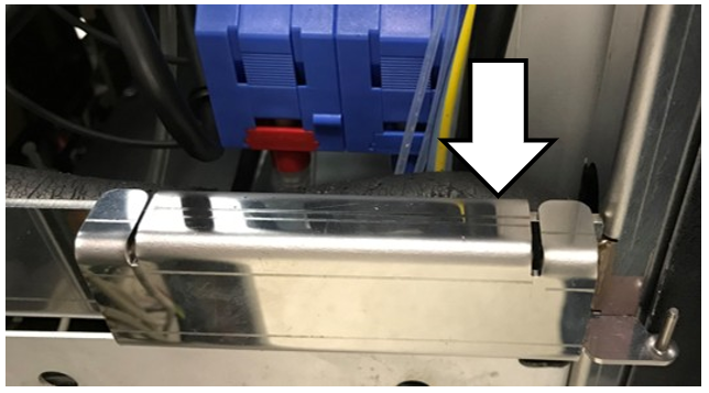
- Remove the door mounting brackets on the front right-side of the Panther.
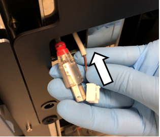
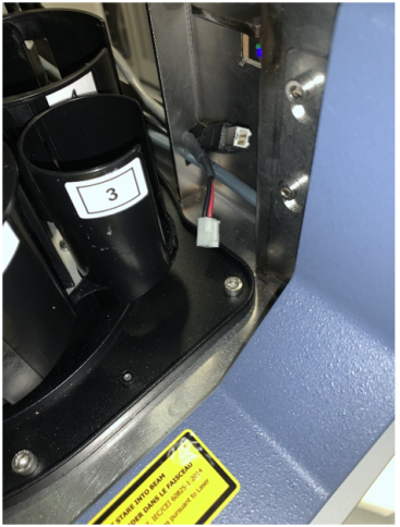
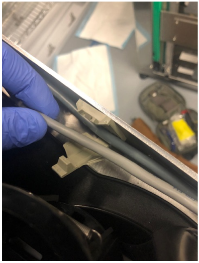
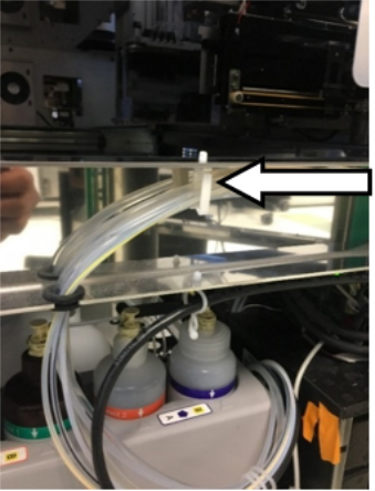
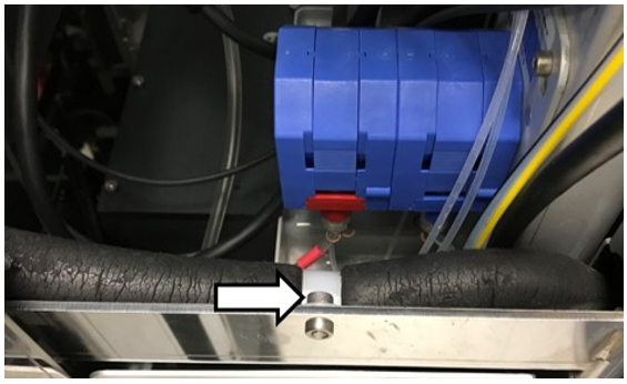
- Remove the tube harness by collapsing the tabs and pushing down on the clip.
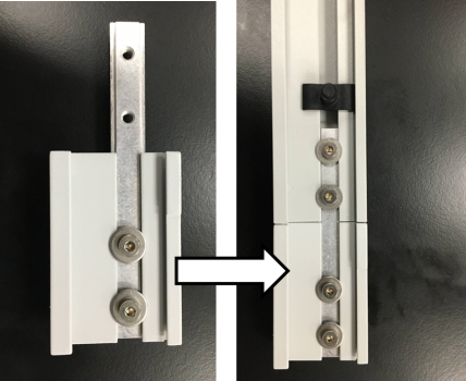
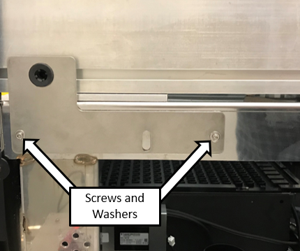
- Attach the L-bracket with the short-end pointing up, as shown below, using the included 2 screws and 2 washers.
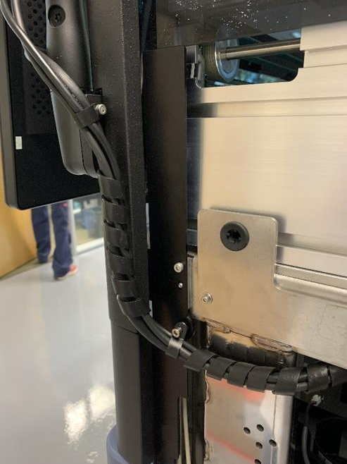
- Install the new trim piece with screw removed in the previous step, into the top hole.
- Reroute the monitor cables, loosely install the lower and upper cable clamps, and connect to the monitor.
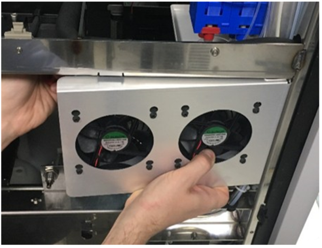
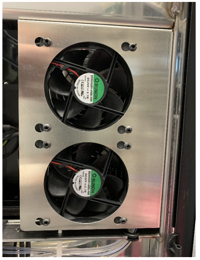
- Reorient the Chassis Fan
- Attach the Hinge Plate to the Panther Chassis.
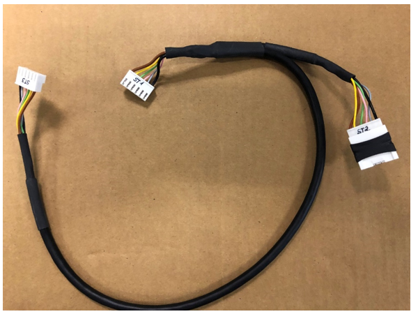
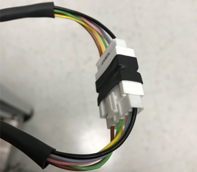
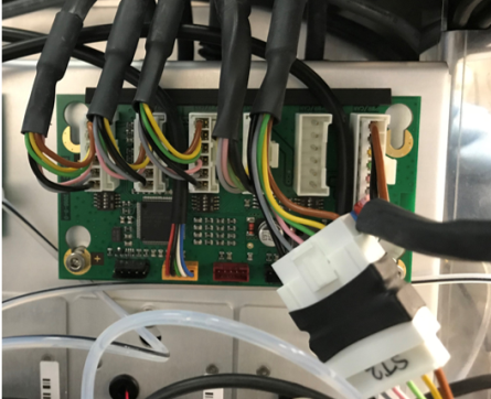
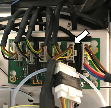
- Install the Y-splitter CAN cable
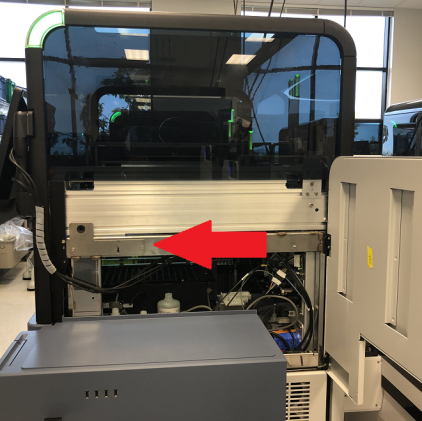
- Remove the Input Queue.

Note—If the Input Queue will be returned, decontaminate and complete Decon/OBF/RMA Form [19-02-APX-A]. Save the front and back mounting screws for installation of the MTU Queue in later steps. 
Leave the front cover removed to install the MTU Queue. - MTU Queue Installation
 button at the top of the page to send feedback, comments, or change requests.