Programming the Firewall
This procedure applies to the Cisco ASA 5505 and Cisco ASA 5506 Firewalls.

|
Caution—If you are setting up a System with LINK, a 5506 is required. |

|
Note—
Screen shots below are for reference ONLY. Your screens may differ.
All information entered into the Firewall Wizard will come from the Panther Site Assessment.
Only steps that require further action are described.
If selecting no and no further input is needed, it is not described.
|
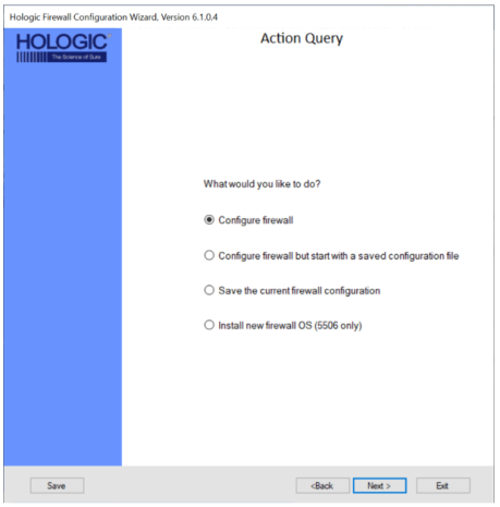
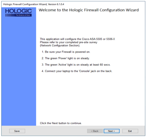
 Open the Firewall Wizard.
- Confirm Steps 1-4 have been completed and Click Next >.
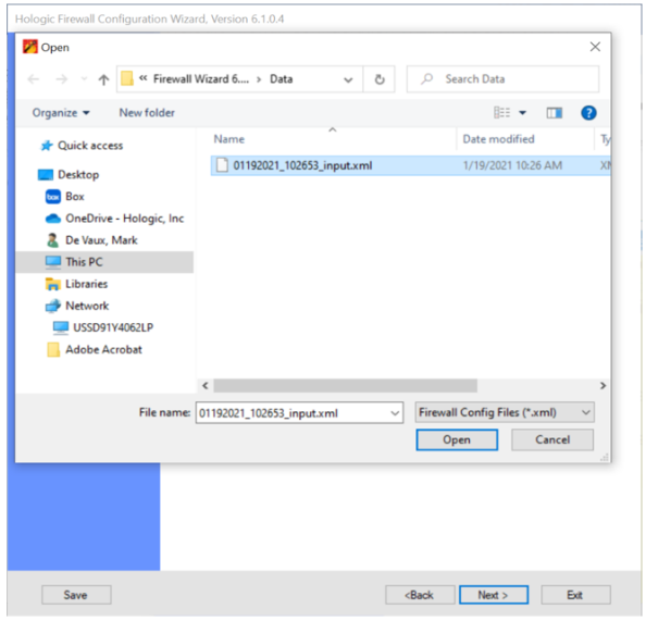
- Select what action you would like to perform.
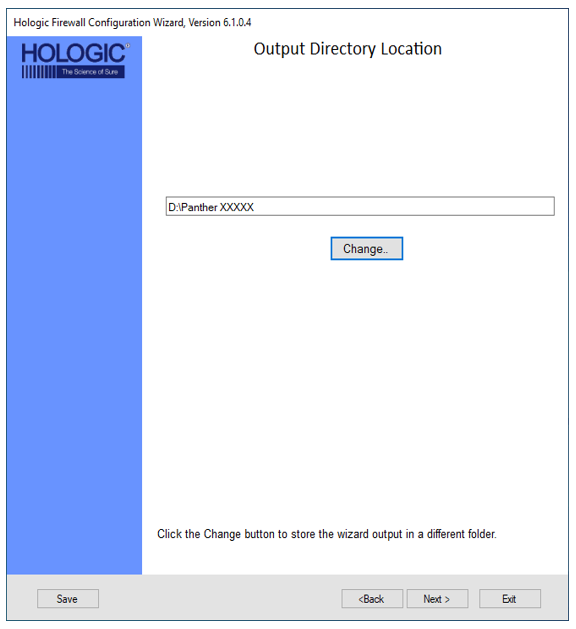
- Select Output Directory Location
- Click Next if the default location is acceptable
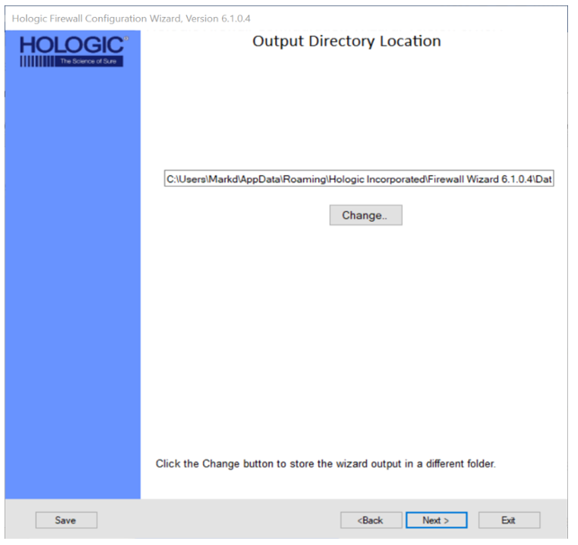
- To select a different location Click Change
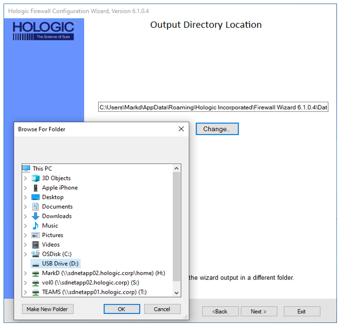
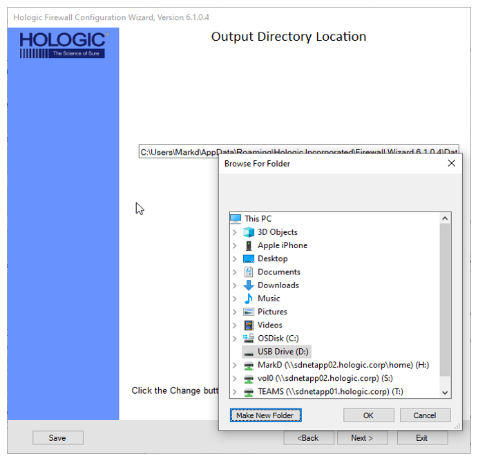
- Click Make New Folder
- Type in the folder name and click OK
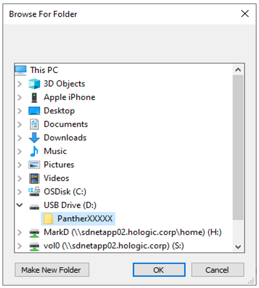
- Click Next
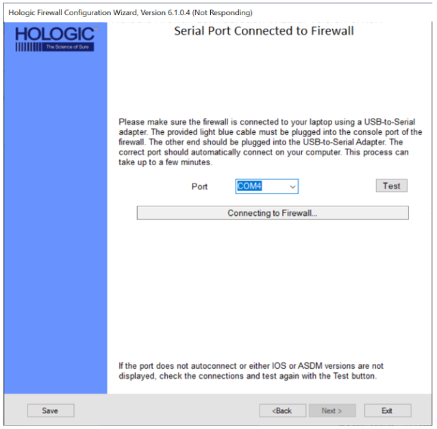
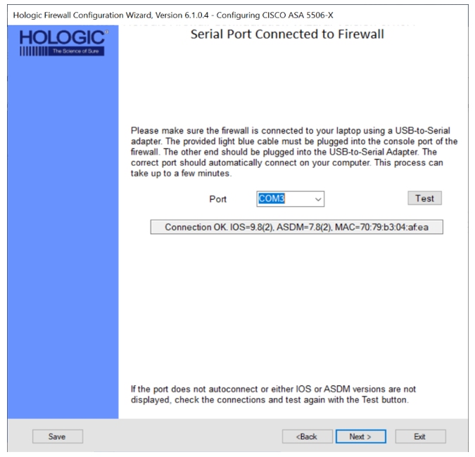
- Verification of Firewall SW connection to your laptop
- Site Information
|
|
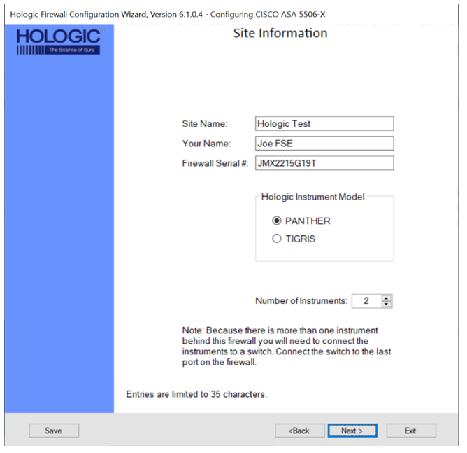
Note— By filling in the Site Information page, the wizard will program and record where the firewall is installed and who installed it.
This information is programed directly onto the firewall and listed in an instructions.txt file as an output of programing the firewall. |
Fill in the following fields.
- Site Name
- Your Full Name
- Firewall Serial # - located on the bottom of the firewall
- Select the Panther radio button in the Hologic Instrument Model box.
- Enter the number of instrument that will be connected to the Firewall.
| Note— A maximum of 16 Systemss can be connected to the Firewall. |
- Click Next >.
- Cisco Syslog Setup
|
|
Note—
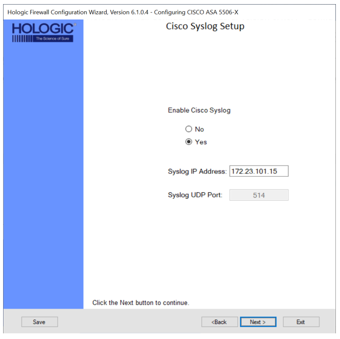
Cisco network devices use Syslog to send system messages and debug output to a local logging process inside the device.
Cisco Syslog is a standard for logging messages.
Syslog allows the customer's IT/IS to monitor what the firewall is doing.
|
- Select Yes if the customer requests Syslog to be enabled.
- Enter the appropriate IP Address and Port.
- Click Next >.
- Windows Update Server
|
|
Note—
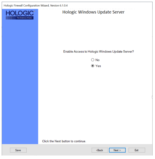
The Windows Update Server will be used to send Windows Updates that are needed to fix vulnerabilities in the Windows Operating System.
This will allow connected Panther Systems to install Operating System updates and provide protection against newly discovered vulnerabilities. |
- Select Yes if the customer requests Windows Update Server to be enabled and click Next >.
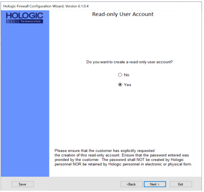
- Read Only User Account
|
|
Note—
The Read-Only User Account allows a customer to read the Firewall's configuration but does not allow them to modify settings.
The Read-Only User Account allows the customer's IT to access the Firewall with Read Only privileges and view the configuration.
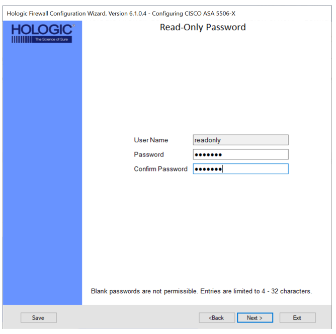
The User Name will always default to "readonly" and may not be changed. Passwords must contain 4 to 32 characters.
|
- Select Yes, if the customer requests a Read-Only User Account and click Next >.
- Enter the password provided by the Customer in both the Password and Confirm Password fields and click Next >.
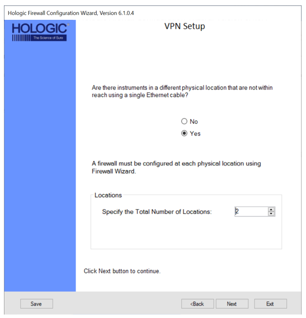
- VPN Setup (Only applicable on the 5506)
|
|
Note— VPN connections are only necessary at customer sites when Panthers are physically separated and cannot be physically connected to a single switch.
If the customer’s ethernet infrastructure allows separated Panthers to be connected to a single switch, VPN is not needed. The maximum number of VPN connections is 10. Each physical location will require a Firewall installed.
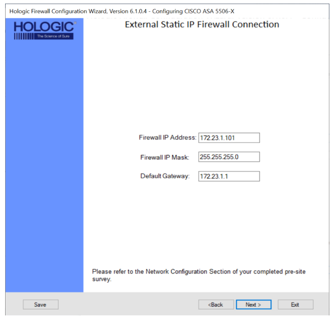
If setting up a VPN, the external IP addresses of each Firewall MUST have a static IP address provided by the customer. |
- Select Yes, if the customer has Panthers at different physical locations that are to be connected.
- Specify the total number of locations (Firewalls) and click Next >.
- Enter the External IP Address, External IP Mask, and External Gateway IP for each location and click Next >.
| Caution— Make sure you select Current Firewall for the Firewall you are programming. |
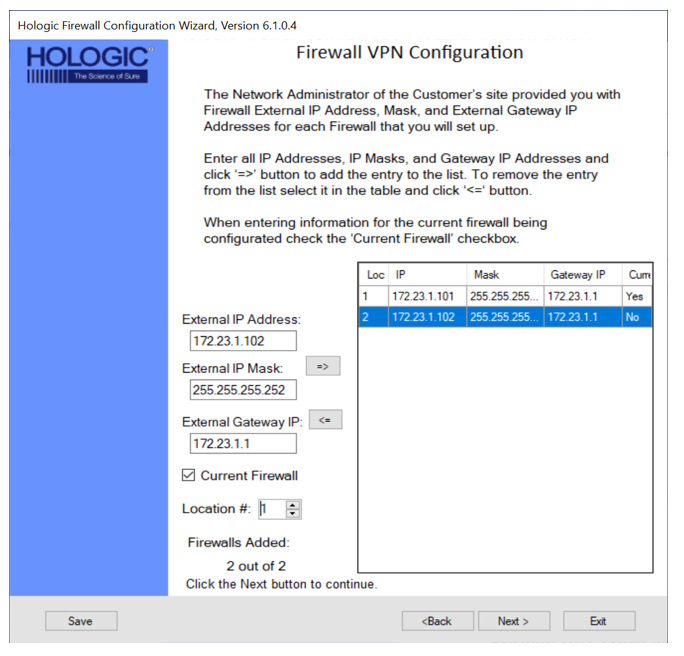
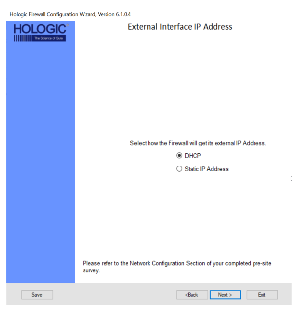
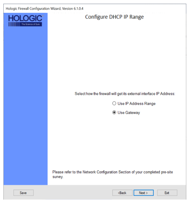
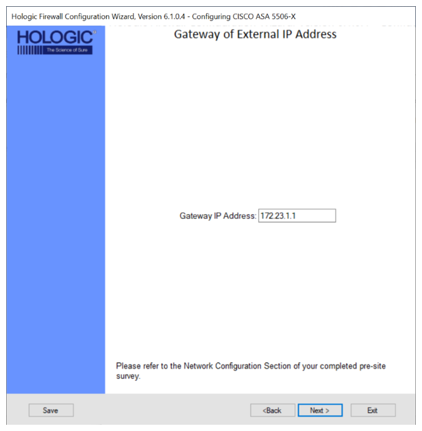
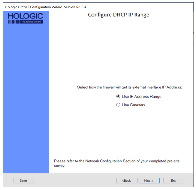
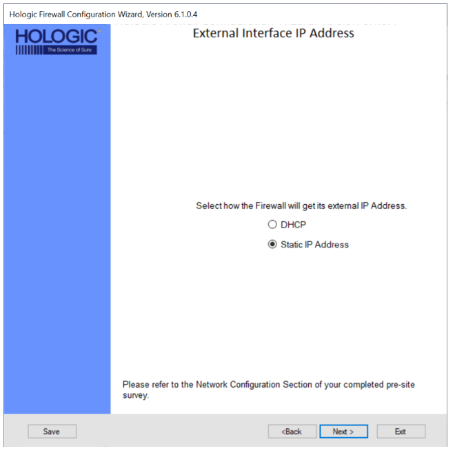
- External Interface IP Address
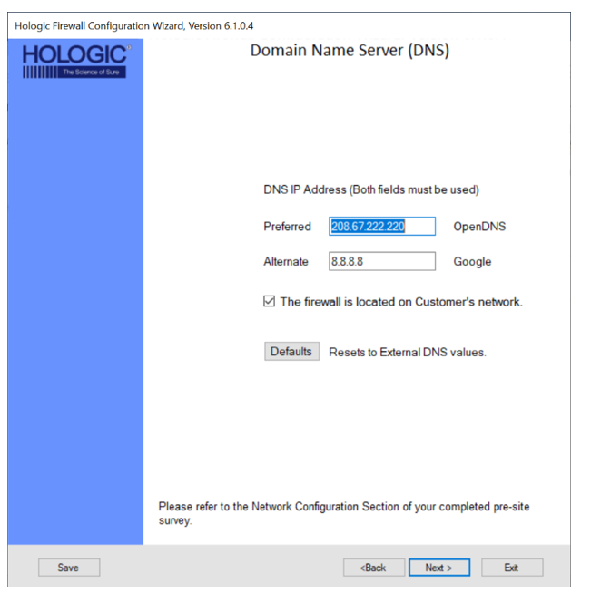
- Domain Name Server (DNS) Settings
|
|
Note—
A Domain Name Server is used to resolve a hostname such as connect.hologicsecurecare.com to an IP address.
OpenDNS (208.67.222.220) and Google DNS (8.8.8.8) are pre-filled as default by the Wizard.
|
- Verify the check mark box is selected for:

| Note—This should only be unchecked if connecting to the Hologic Network (internal) |
- Populate a new Preferred DNS in the text box if one is provided.
- Populate a new Alternate DNS in the text box if one is provided.
- Click Next >
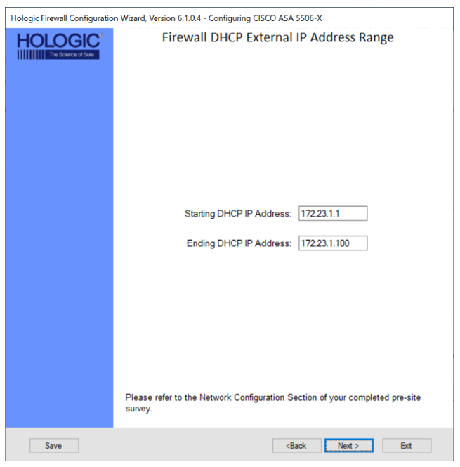
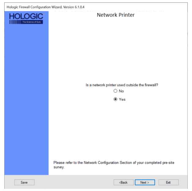
- Network Printer
|
|
Note—
There are two possibilities for networking the printer.
Option 1 is to network through the customer network.
An IP Address for the printer will be required from the customer.
Option 2 is to network within the Hologic network.
If Option 2 is needed, select NO when asked if the network printer will be used outside the firewall.
If the customer does not want the network printer on the customer’s network, there is the option for the printer to be connected to the switch.
Configure the IP address of the network printer to be 172.23.1.99,
subnet 255.255.255.0 and Gateway of 172.23.1.1 |
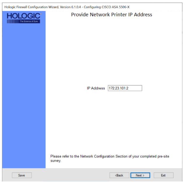
- Select Yes if the customer requests a Network Printer.
- Enter the IP Address of the Network Printer and click Next >.
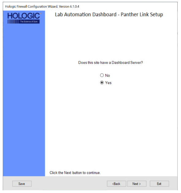
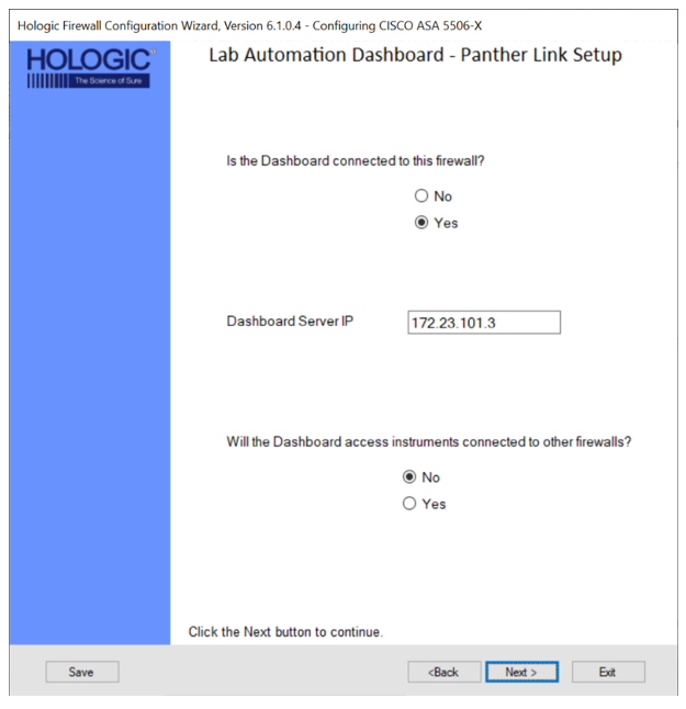
- Panther Link Dashboard Setup
|
|
Note— Panther Link allows multiple Panthers to share a common database
If setting up a Dashboard Server, a Cisco ASA 5506 MUST be used.
The Dashboard Server requires a static IP address on the customer’s network which will use NAT to connect to an internal Panther network IP address.
During this setup, the external (customer network) NAT IP address will need to be mapped.
The instructions.txt file will hold the necessary IP address and ports that will be used during configuration of the Dashboard server.
|
- Select Yes if the customer requests to be connected with Link Dashboard and click Next >.
- Select Yes If the Dashboard Server will be connected to the Firewall currently being configured.
- Enter the Dashboard Server IP.
- Select Yes if the Dashboard Server will need to access Panthers connected to other Firewalls and click Next >.
| Note— Only needed for VPN setups |
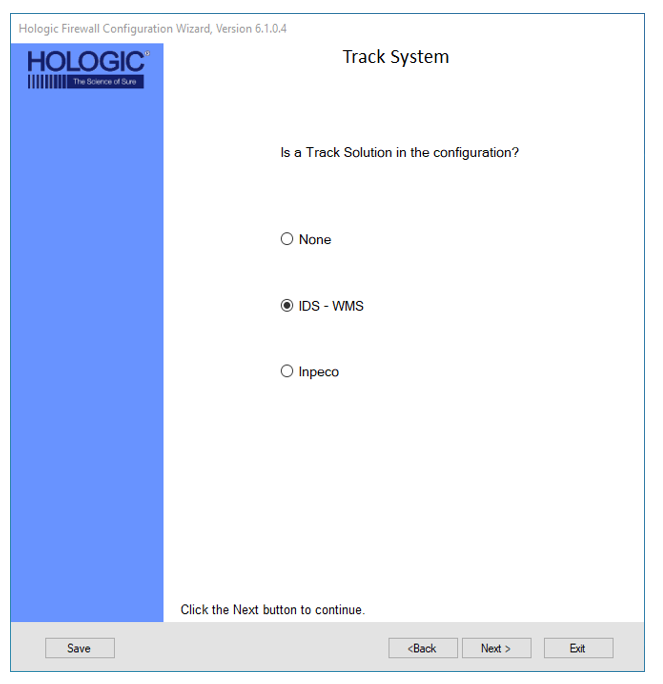
- Track System
|
|
Note—
With the addition of Track Systems, new network connections are required.
The Panther has integrated with two different track systems, IDS and Inpeco.
|
|
|
Note— IDS
The Panther Trax solution requires network connections with WMS using an IDS track.
IDS does not require any additional input.
|
|
|
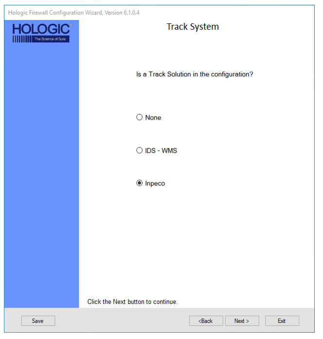
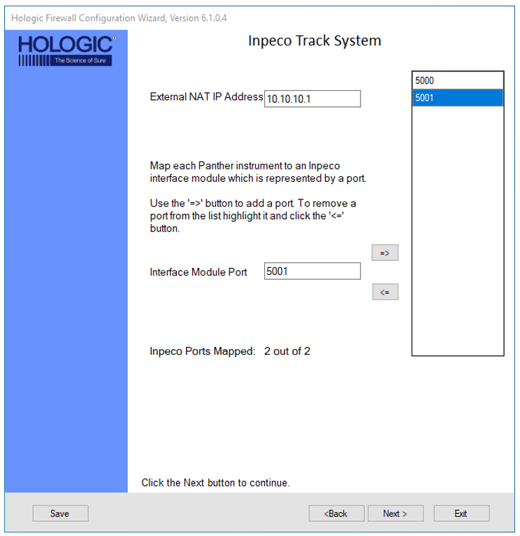
Note— Inpeco
The Panther Track Ready System has the compatibility to be integrated and connected to a pre-existing Inpeco Track System. To connect to the Inpeco System, the customer technical support admin or the Inpeco Track System service organization will supply an External NAT IP Address as well as a dedicated port for each Panther that is to be connected to the track system. |
- Select IDS-WMS if an IDS track will be connected to the firewall and Click Next >.
- Select Inpeco, if an Inpeco track will be connected to the firewall and click Next >.
- Enter the NAT IP Address for the Inpeco system
- Enter in the Interface Module Port for each Panther, then select the Right arrow to add to the defined Interface Port List until all ports are mapped and click Next >.
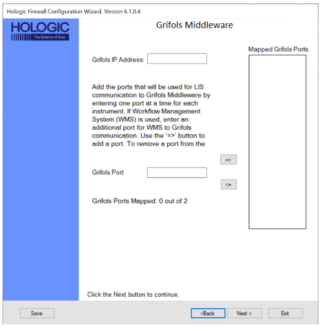
- Grifols Middleware
|
|
Note— Not for Hologic Track systems |
- Select the Yes button if the customer is using Grifols Middleware and click the Next >

- Enter the Grifols IP Address then add the appropriate number of ports (ONE per System) and click Next >..
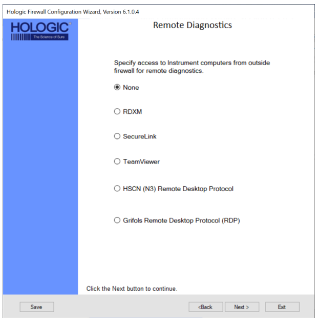
- Remote Diagnostics
|
|
Note—
TeamViewer and Grifols Remote Desktop Protocol (RDP) are only used by Grifols.
RDXM and SecureLink Do not require any additional input.
SecureLink will only work with System SW v7.2 and above
You cannot connect multiple systems on a single firewall if they use SecureLink (System SW v7.2 and above) and RDXM/Pro360 (System SW v7.1 and below).
All systems with System SW v7.2 and above (SecureLink) can be connected on 1 Firewall.
All systems with System SW v7.1.5.4 and below (RDXM/Pro360) can be connected on 1 Firewall.
|
- Select the Remote Diagnostics method to be used at the customer site and click Next >.
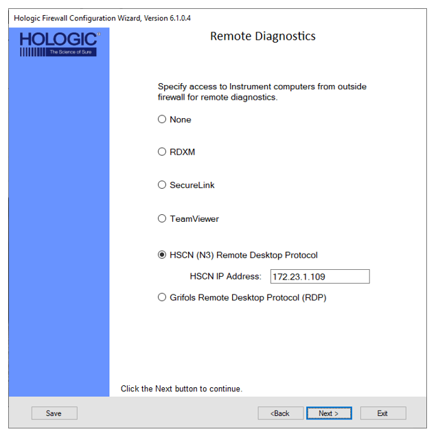
- HSCN (N3) Remote Desktop Protocol
| Note— This is for UK NHS Network Only |
- Select the HSCN (N3) Remote Desktop Protocol radio button.
- Enter the HSCN IP Address and click Next >.
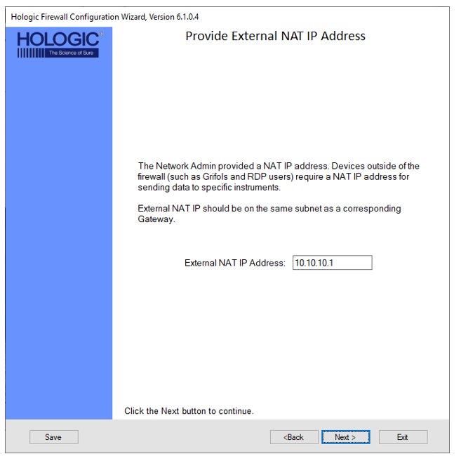
- Enter the External NAT IP Address and click Next >.
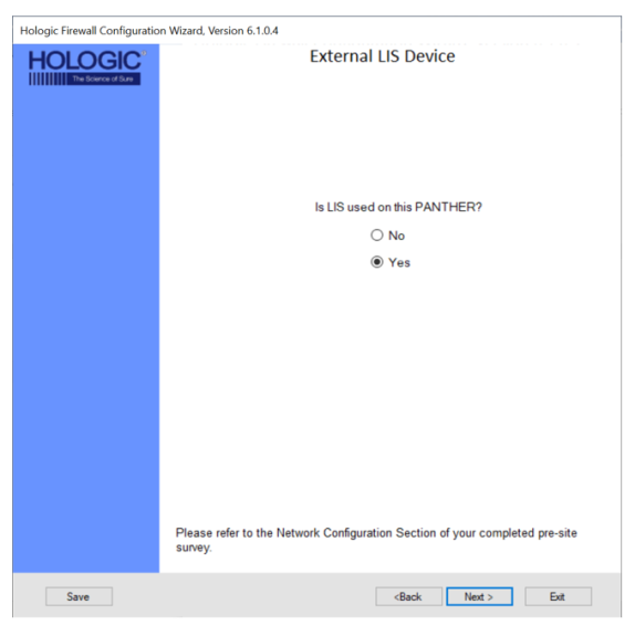
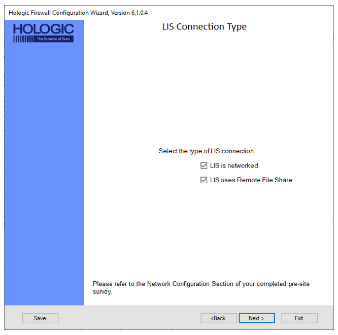
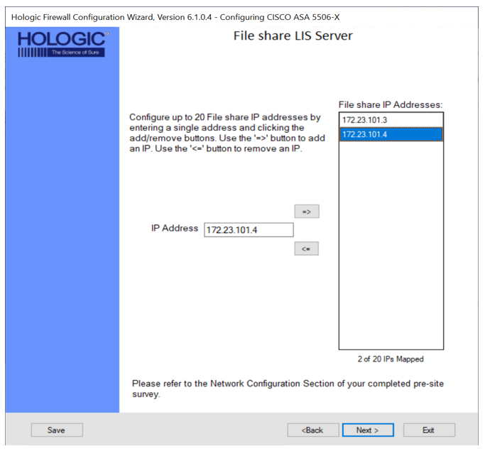
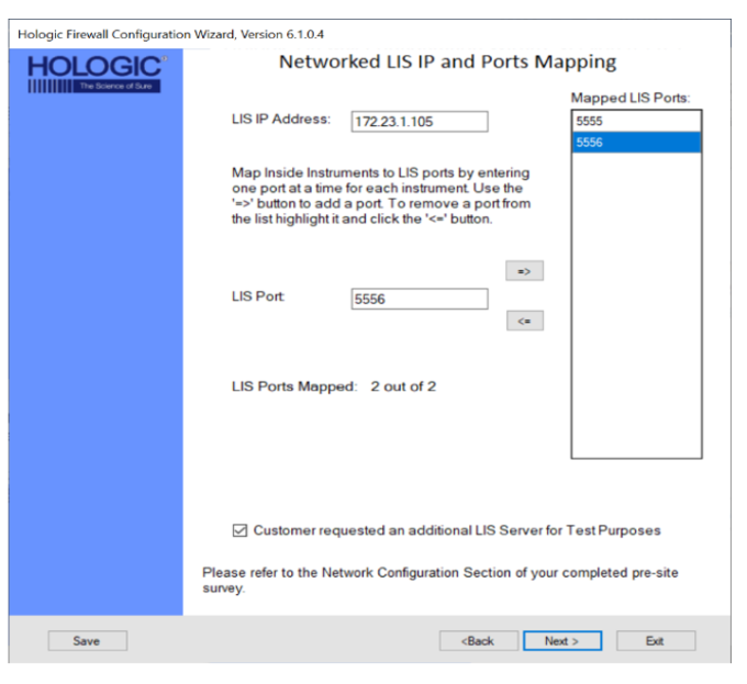
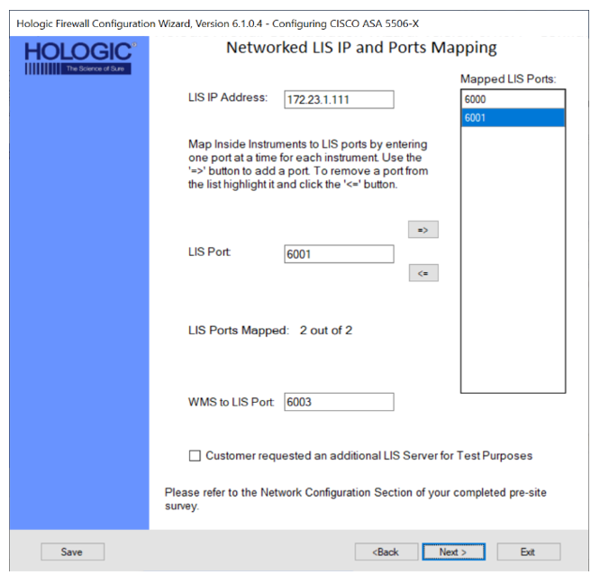
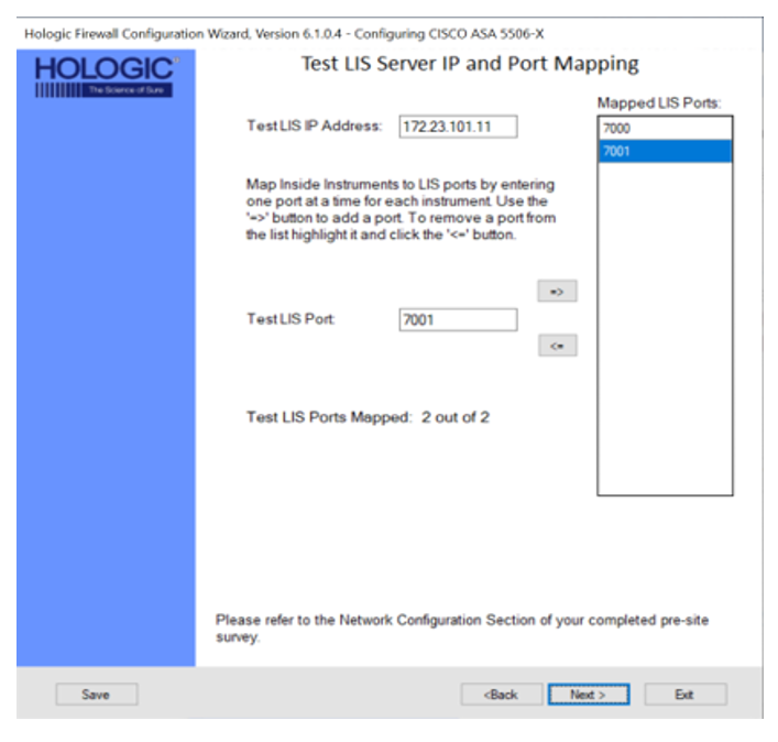
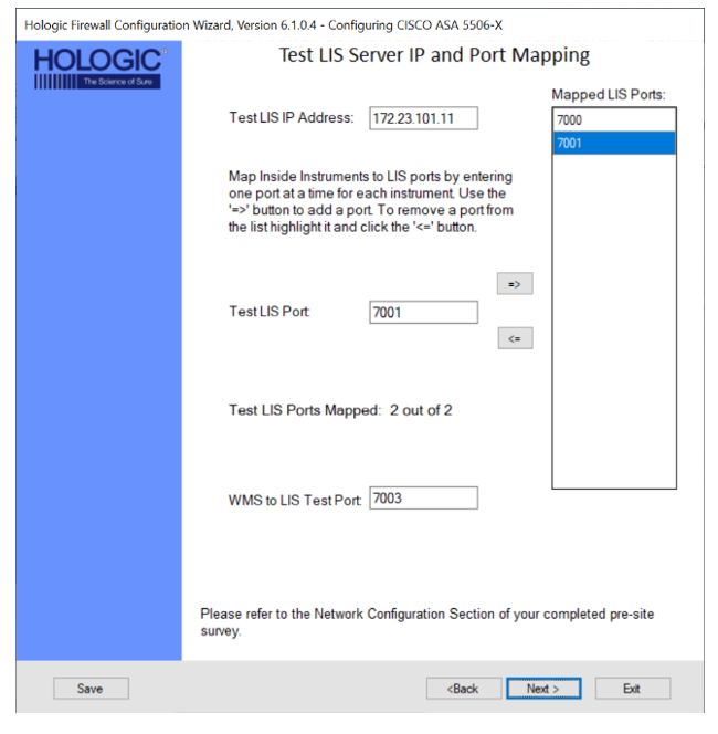
- Laboratory Information System (LIS)
- Review Your Input
- Review your input
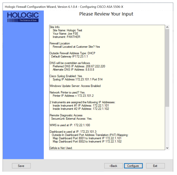
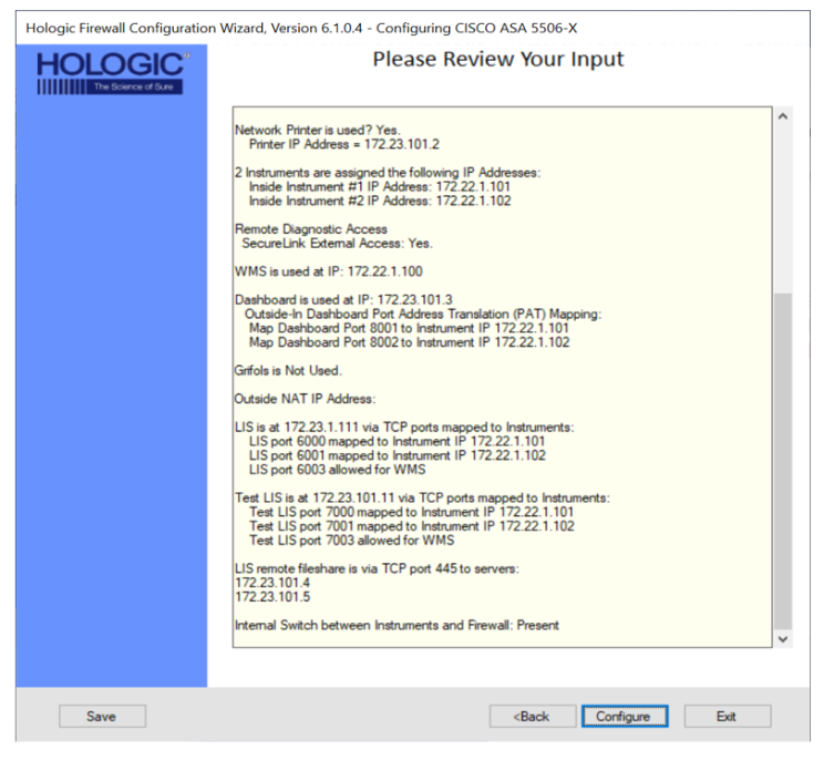
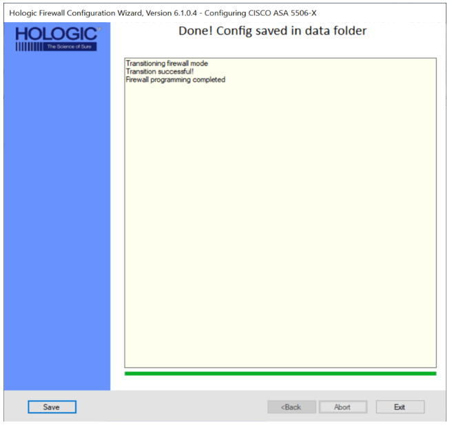
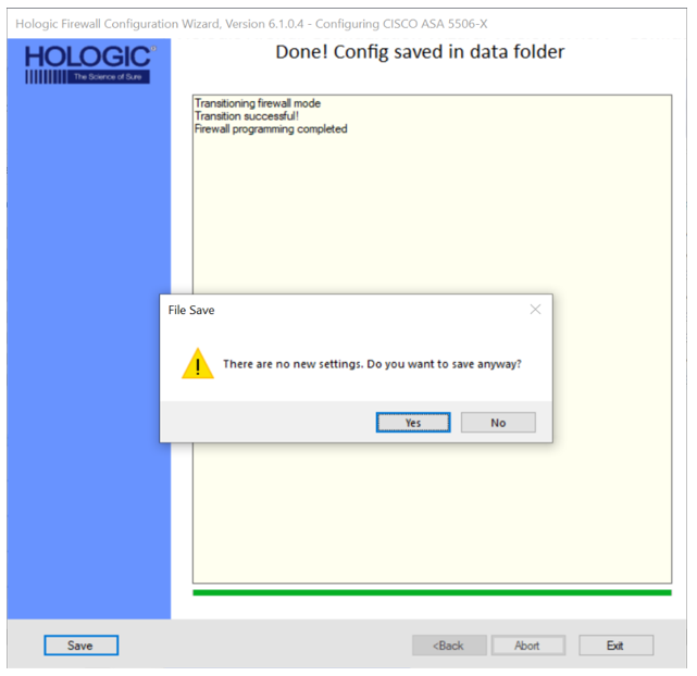
- Select Configure.
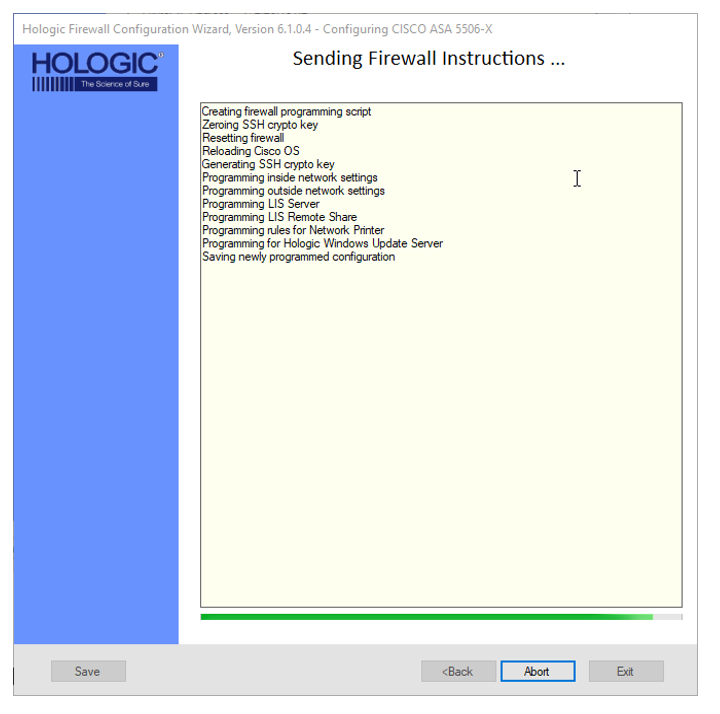
| Note—DO NOT click the Abort button unless it is necessary to cancel the configuration. |
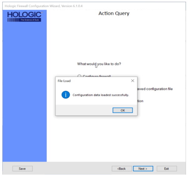
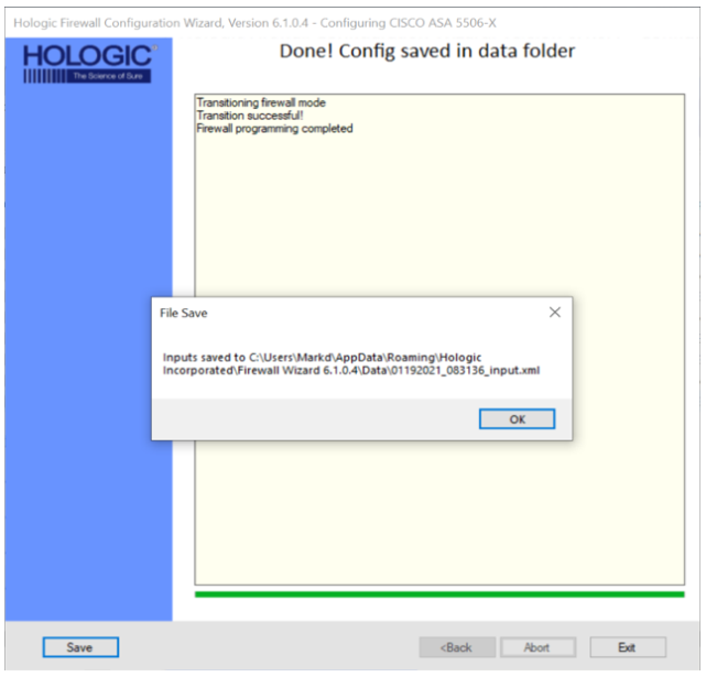
- Once configuration is complete, verify settings are correct and click OK.
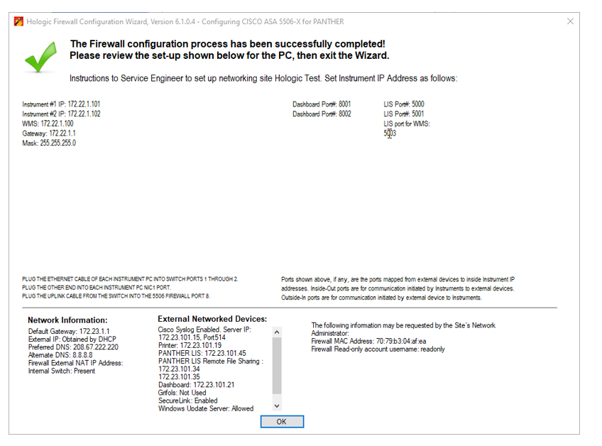
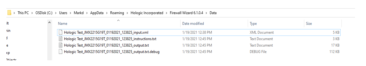
- Upload the 4 Configuration files shown below to the SR in Oracle OR the Panther Asset page in H1.
- Proceed to Setting a Panther IP Address on the Panther Workstation
Click the  button at the top of the page to send feedback, comments, or change requests.