Parts and Materials Required
- VACUUM PCB
Time Required
- 30 minutes
Removal Procedure

|
Note—In the following PCB removal/replacement procedure, the vacuum module is left inside the system. If desired, the module can be taken out for servicing. |
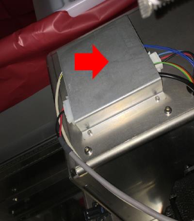
 Remove the sheet metal cover that is protecting the red PCB on top of the vacuum housing.
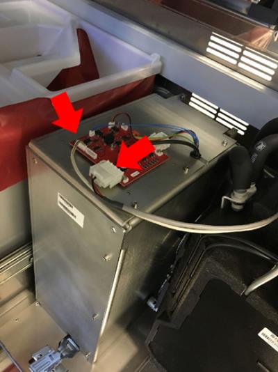
- Disconnect the power cable and control cable from the front of the PCB.
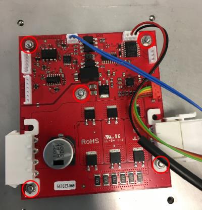
- Disconnect the four remaining cables from the pump. Label if necessary to ensure each cable is reconnected in the same place on the new PCB. Then remove the five 5.5 mm nuts that hold the PCB in place.
- Remove the PCB from the top of the vacuum housing. DO NOT remove the gold spacers.
Note—The PCB could be slightly stuck to the soft grey pad underneath it, gently use a flat head screw driver to pry it off if necessary.
Replacement Procedure
- Insert the new PCB onto the threaded pin slots and tighten down the five 5.5 mm nuts. The PCB only fits one way. Then re-connect all 4 cables coming from the pump.
- Re-connect the power and control cables.
- Place the sheet metal cover back on top of the PCB. Screw down the 4 screws that hold the sheet metal cover in place.
 button at the top of the page to send feedback, comments, or change requests.