Vacuum Module (Configuration 3) Removal and Replacement
Parts and Materials Required
- Panther Tool Kit
- Vacuum Module (Quad Head)
- Pump, Quad, Vacuum System
- Vacuum, Power Cable with Fuse and Ferrite
- PCB, Vacuum System, Quad
- Fan, Vacuum System, Quad
- Assy, Vacuum, Muffler
- Vacuum System Quad Pump, Signal Cable
Time Required
Removal Procedure
- Put on proper PPE.
- Prepare a clean and flat work space covered with bench pads.
- Power down the Panther System.
 Locate the Universal Fluid Drawer.
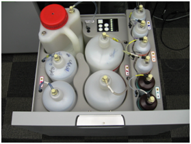
 | Note—It is not necessary to remove or disconnect all the fluid bottles to perform the procedure. |
| Note—It is also not necessary to remove the front cover of the Universal Fluid Drawer. If left in place, find a box or similar object to provide some support when the drawer is removed from the rails. |
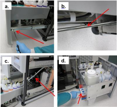
- Remove the Universal Fluids Drawer as shown below:
- Free the drawer from the slides in the front (left side and right side) by twisting each front tab up with a flathead screwdriver.
- Supporting the drawer, push the slides back. Then pull drawer forward to unhook from back horizontal tabs.
- Turn the drawer to the side and move out of the way. Do not stretch or strain any tubing.
- Set the drawer on an appropriately-sized supporting object. (If front cover was removed, the drawer can sit flat on the floor.
- Unlatch the vacuum module from the Panther chassis.
- Slide the vacuum module toward the front of the system.
- Disconnect the Vacuum Hose, Signal cable, and Power Cable.
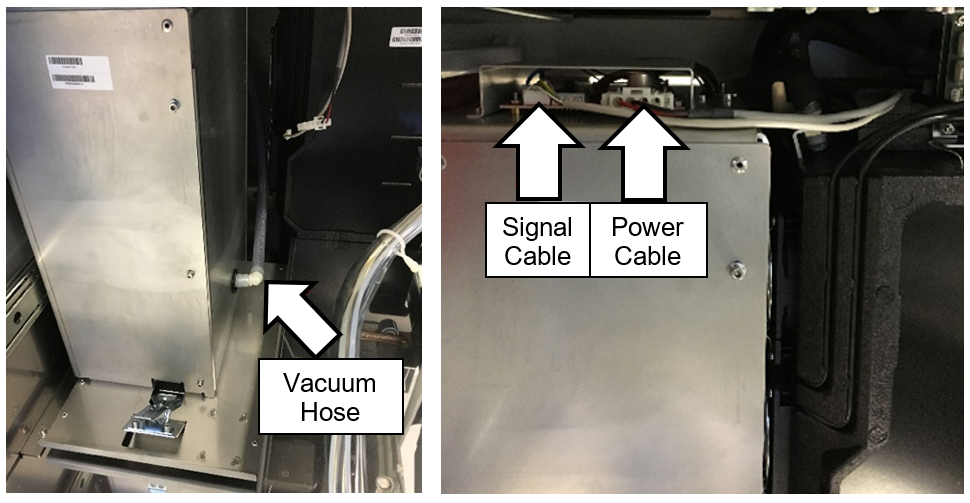
- Slide the Vacuum Housing out of the Panther System and place on Blue Pads.
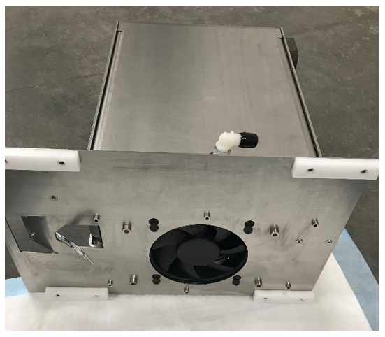
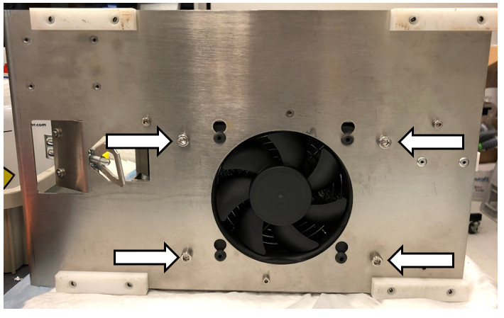
- Unscrew the 9 screws securing the front plate of the Vacuum Housing.
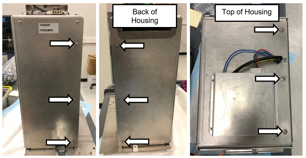
- Place the Vacuum Housing on its back as shown in the picture below.
- Unscrew the last screw securing the front plate to the housing.
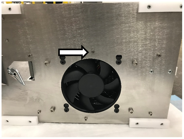
- Remove and set aside the front plate.
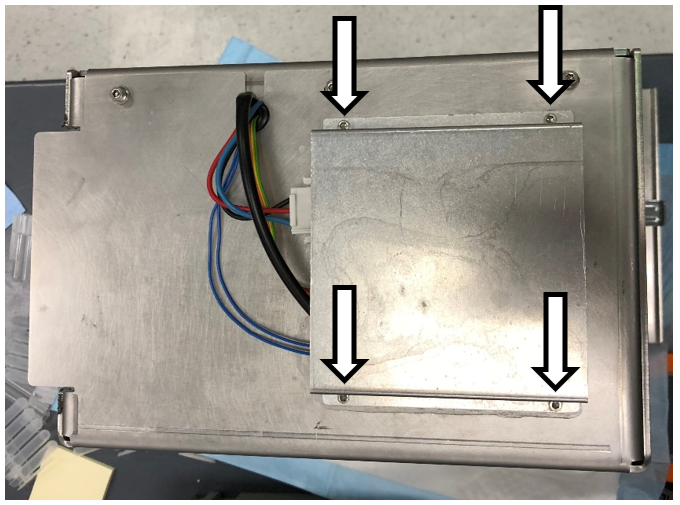
- Unscrew the 4 screws securing the top cover for the PCB.
|
|
Note—Set the PCB cover aside. |
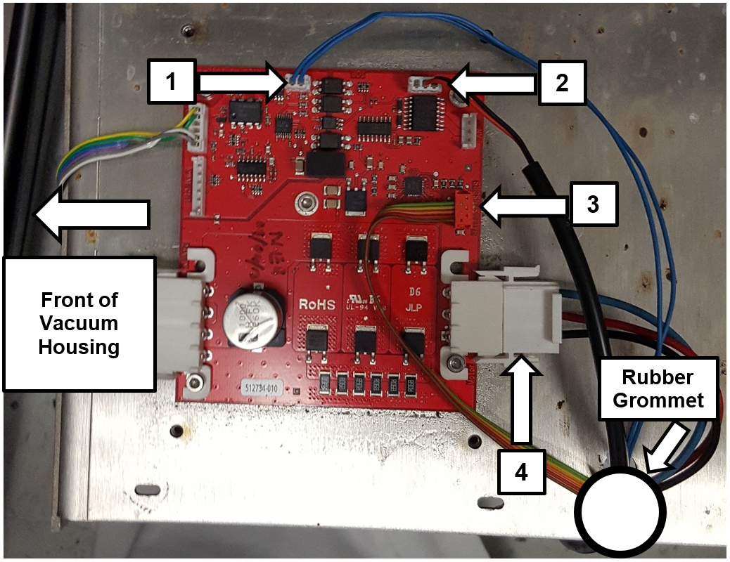
- Disconnect the 4 cables shown below (labeled 1, 2, 3, and 4) connecting the Pump to the PCB.
- Remove the rubber grommet.
- Unscrew the 4 screws shown below on the bottom of the slide plate.
|
|
Note—Lay the Vacuum Housing on its back to make it easier to access these screws. Return the housing to an upright position when finished. |
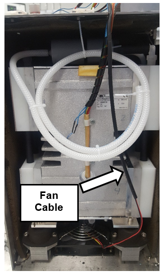
- Slide the Quad Head Pump out of the housing.
|
|
Note—Be careful not to pull the fan cable when sliding out the pump assembly. The fan is mounted to the Vacuum Housing. |
Replacement Procedure
- Reverse the removal procedure.
Verification
- The vacuum level must read between -203mbar and -270mbar and the vacuum pump speed must read above 1650rpm.
If needed refer to Configuring the Quad Head Vacuum Pump Speed.
- Using Service Software or the Panther System main software, initialize the system and verify that vacuum level is within range.
Click the  button at the top of the page to send feedback, comments, or change requests.