Parts and Materials Required
- VACUUM PCB
Time Required
- 30 minutes
Removal Procedure
- Put on proper PPE.
- Power down the Panther System.
- Open the Universal Fluids Drawer. (The UFD does not have to be removed for this procedure.)
- Locate the Vacuum Pump PCB located on either the back left or front corner of the vacuum base.
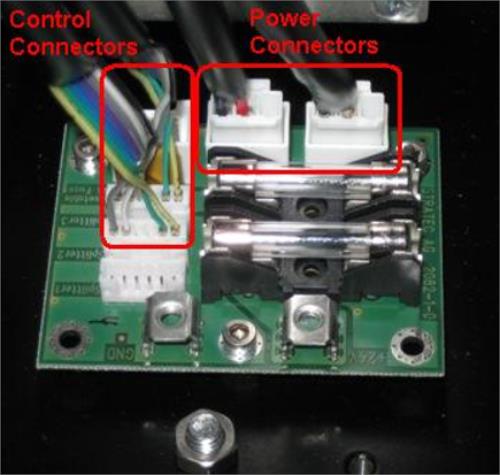
 Remove the Power Connectors and Control connectors as shown. Carefully unlatch and slide the vacuum module forward if it helps to get access to any connections in the back. STOP sliding the module forward if it puts stress on the cables.
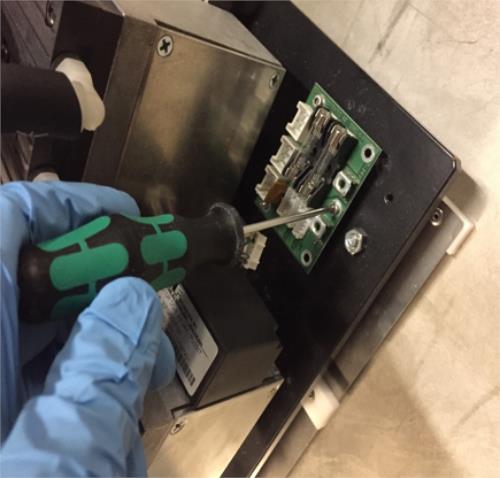
- When all cables have been disconnected, slide the module forward to get access to the PCB. Using a 2.5 mm hex driver, remove the 3 screws on the PCB. (Module is shown out of the system, but can be left in for the procedure.)
- Remove the PCB.
Replacement Procedure
- Reverse the removal process to install the new PCB.
 button at the top of the page to send feedback, comments, or change requests.