Pipettor Z-Axis Flex Cable Removal and Replacement
Parts and Materials Required
- Proper PPE
- Hex Key, 2 mm
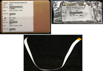
 PIPETTOR, REAGENT, Z-AXIS FLEX CABLE
or
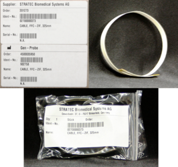
- PIPETTOR, SAMPLE, Z-AXIS FLEX CABLE
Time Required
- 20 minutes - Auto-Teach
- 10 minutes per arm for PI Test
- 30 minutes per arm for BLDC/CLLD
Removal Procedure
- Put on proper PPE.
- Power down the Panther System.
- Orient the pipettor arm to an easily accessible position. Be sure the DiTi cone is away from other modules and parts of the system.
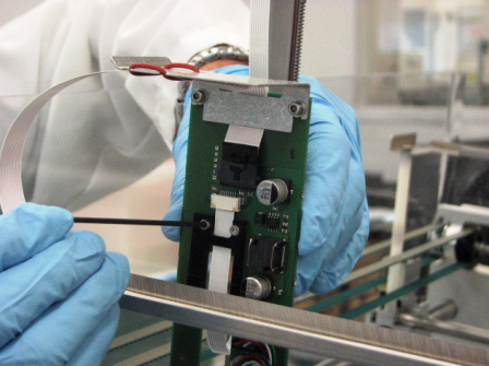
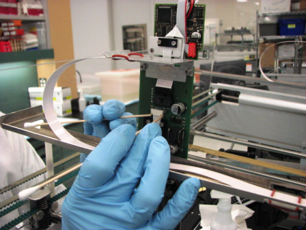
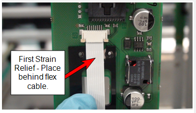
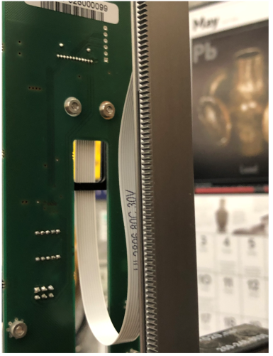
- Remove or loosen the flex cable strain relief on the pipettor main PCB for easy removal of the flex cable.
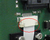
- Carefully remove the flex cable connector clamp by pulling down evenly on the two tabs.
This will release the flex cable from the pipettor main PCB. - Pull the cable down and out of the connector clamp.
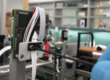
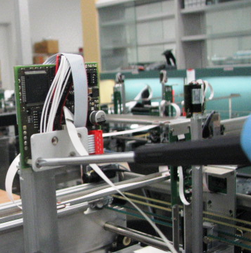
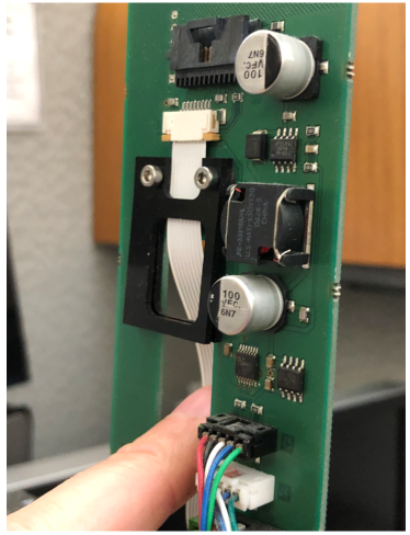
- Remove the flex cable strain relief from the pipettor pump PCB.
- If replacing the Sample Pipettor arm flex cable, remove the bracket and flat cable connection for access to the flex cable clamp on the pipettor pump PCB.
- As explained in Steps 5 and 6, remove the flex cable from the pipettor pump PCB and the flex cable connector clamp.
- Discard the old cable or save for failure analysis.
Replacement Procedure
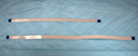
- Prepare the new flex cable (long cable is for sample arm, shorter cable is for reagent arm).
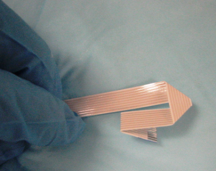
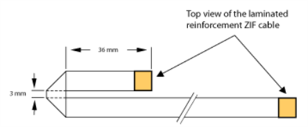
- For the Sample Pipettor arm cable only, fold exactly according to sample arm flex cable folding instructions.
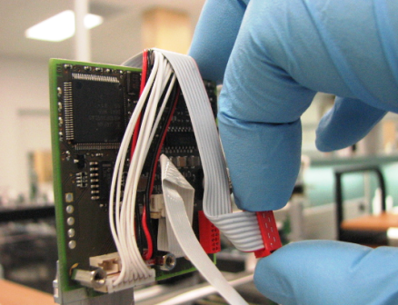
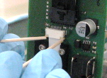
- Insert the new flex cable into the pipettor pump PCB by inserting the exposed cable contact side into the cable clamp. Repeat the insertion method on the opposite side of the cable into the pipettor main PCB.
- Secure the clamps by carefully and simultaneously (as best as possible) closing the clamp tabs.
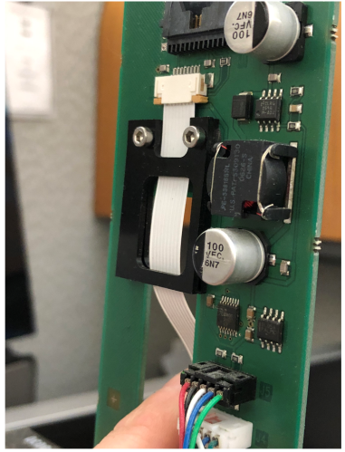
- Reinstall the flex cable connector and bracket.
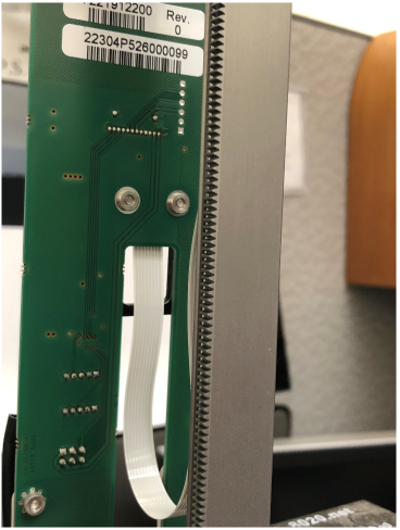
- Be sure that the flex cable is able to move freely and perpendicular with the pipettor arm before fully securing the strain reliefs.
 button at the top of the page to send feedback, comments, or change requests.