Parts and Materials Required
- Hex key, 2.5 mm
- OUTPUT Q/LUMO, INJECT OLV/DISP VER PCB
Time Required
- 45 minutes
Removal Procedure
- Put on proper PPE.
- Power down the Panther System.
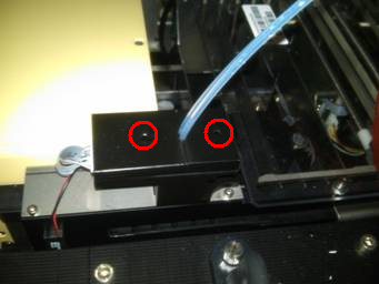
 Using a 2.5 mm hex key, unscrew the two screws that secure the two OLV covers.
- Remove both covers from the OLV board.
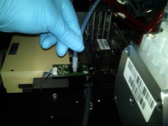
- Remove the injector and place it on an absorbent pad.
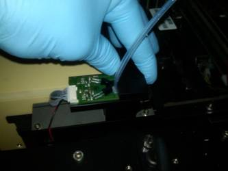
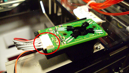
- Unplug the connector to the OLV PCB.
- Remove the OLV PCB.
Replacement Procedure
- Reverse the removal procedure.
- Connect the injectors into the OLV board.
- Replace the OLV board covers and tighten the 2.5 mm screws.
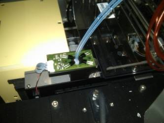
- Visually verify the red outlet fitting of the Peristaltic Pump is routed and connected correctly to the Left position of the Output Queue OLV PCB. Visually verify the blue outlet fitting of the Peristaltic Pump is routed and connected correctly to the Right position of the Output Queue OLV PCB.
- Verify that connections are properly seated and that screws are all in place.
Alignment/Calibration
Verification
- Perform a module Operational Qualification.
- PrimeOperation of pumping fluid through tubing to ensure proper and consistent fluid delivery (remove air from the tubing, etc.). the system (see the Panther System Operator's Manual).
 button at the top of the page to send feedback, comments, or change requests.
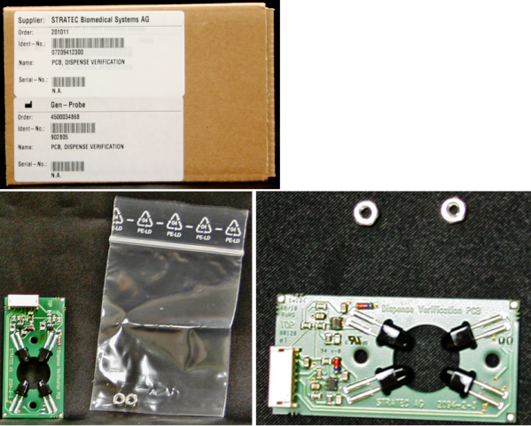