Parts and Materials Required
- Long nose pliers
- INCUBATOR (ALL), INTERNAL PCB (W/SENSOR)
Time Required
- 30 minutes
Procedure
|
|
MTUs may be present in module. It is necessary to remove all MTUs to avoid contamination. |
- Put on proper PPE.
- Remove the Luminometer Injectors.
- Open the Service Drawer.
- Open the Incubator cover and baffle.
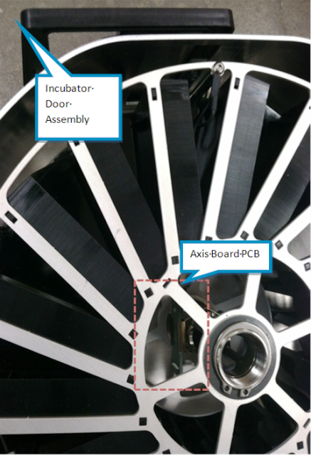
 Locate the Incubator Axis PCB
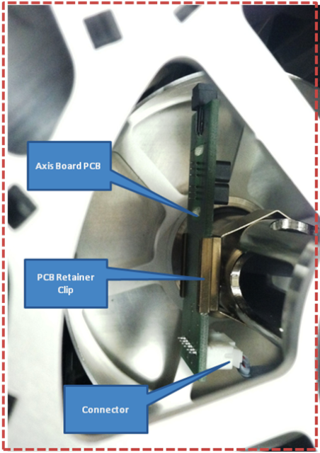
- Using long-nose pliers (or by hand) remove the connector from the Incubator axis PCB.
- Remove the Incubator axis PCB.
Replacement
- Reverse the removal procedure.

Note — Be sure the connector is correctly seated, and the retaining clip is seated and oriented correctly (in relation to the Incubator door).
Alignment/Calibration
Verification
- Using Service Software, place and remove an MTUMulti-tube unit—Container used to process tests in the instrument. An MTU contains five separate reaction tubes. The MTU is moved through the instrument by the linear distributor and includes five tiplets for pipettiing to be used in the mag wash station. to verify that the Incubator axis PCB detects the MTU.
- Initialize the incubator.
- Place an MTU in slots 6, 12, and 18.
- Check MTU presence.
- Verify the MTUs are detected in slots where MTUs are placed.
- Initialize the module and verify that it reaches temperature.
 button at the top of the page to send feedback, comments, or change requests.