Parts and Materials Required
- Proper PPE
- Hex key, 3 mm
- COP module
Time Required
- 15 minutes plus instrument setup time
Removal Procedure
- Put on proper PPE.
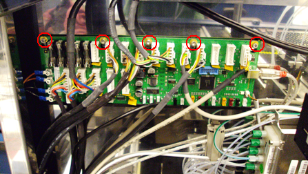
- Locate the COP module inside the Panther System. The COP is located on the top left corner of the back wall inside the Panther System.
 Remove the top five screws that secure the COP module. Not all systems will have five screws.
- Release the COP module from the lip that secures the bottom of the board.
- Remove each cable, one by one, and connect it to the new COP PCB.
- After all cables have been transferred, remove the module.
Replacement Procedure
- Set the DIP switch settings on the replacement PCB so that they match the settings on the removed PCB.
- Reverse the removal procedure.
- The system may recognize the new COP on COM Port 5 but the correct setting is COM Port 3. To verify and/or change the COM Port setting, access the Com Port settings through Windows Explorer:
- From the Panther Shield, open Windows Explorer.
- Right-click on Computer.
- Select Manage.
- Select Device Manager.
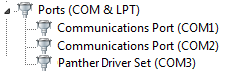
- Expand Ports (COM & LPT).
Panther Driver Set should be set to COM3. If it is not, continue with Step 3f to change the port setting.
- Right-click on the Panther Driver Set (Com X) and select Properties.
- Select the Port Settings tab.
- Select Advanced.
- Select the drop-down next to COM Port Number and select COM3.
- Select OK. If a message appears that says this COM Port is currently in use, change the COM Port anyway.
- Run Instrument Setup (Firmware).
- Install Panther System firmware.
- Open the Pipettor Teaching Software and Transfer Coordinates.
 button at the top of the page to send feedback, comments, or change requests.