Parts and Materials Required
- 3 mm hex key
- 8 mm wrench
- COOLING MODULE ADD-ON SHROUD
Time Required
- 30 minutes
Installation Procedure
- Put on proper PPE.
- Power down the Panther System.
- Open the Panther system right-side door panel.
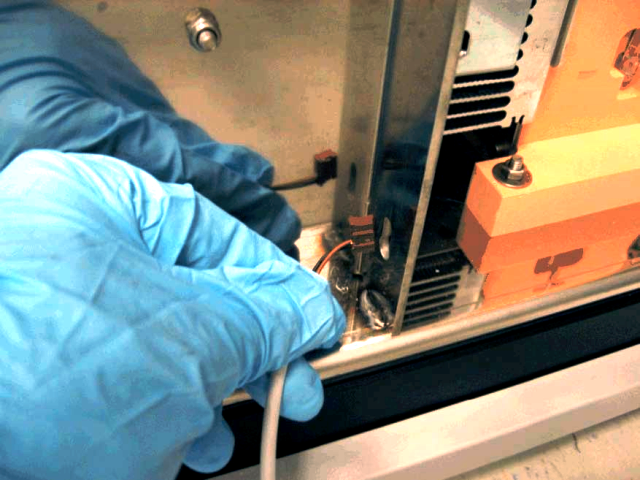
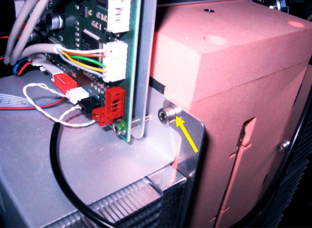
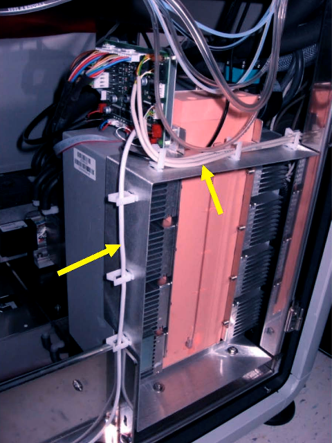
- Locate the Cooling Module at the bottom-right rear corner of the system.
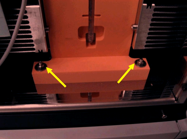
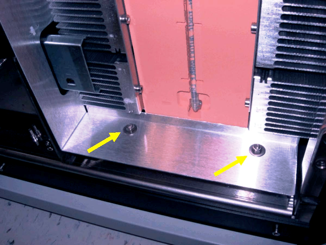
 Using an 8 mm wrench, remove the two mounting nuts and washers.
- Carefully unplug the Universal Fluids Drawer switch cable from the Cooling Module PCB.

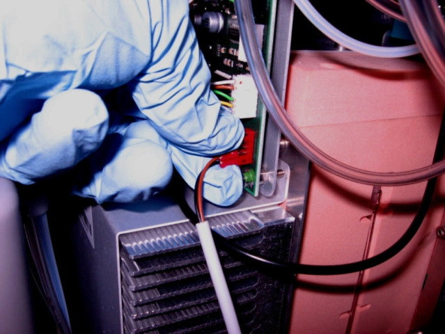
Note — Unplug the connector by only grasping the connector. Do not pull on the wires. - Remove the Universal Fluids Drawer switch cable from the keyhole slot in the rear of the drawer support bracket.
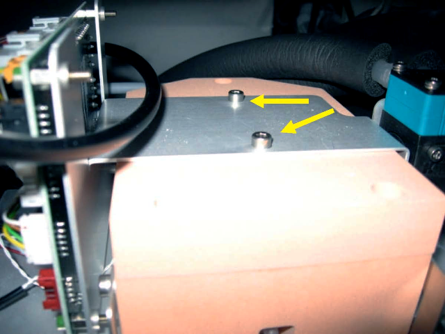
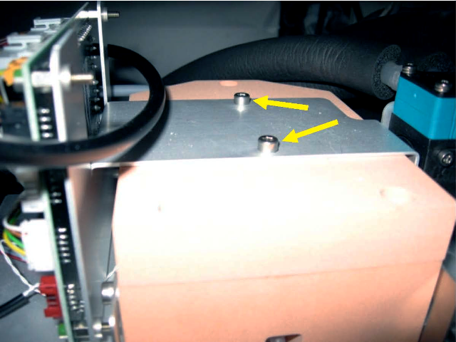
- Using a 3 mm hex key, remove the two screws that secure the Cooling Module PCB bracket to the top of the Cooling Module.
- Slide the PCB bracket back about an inch to access the bracket screws.
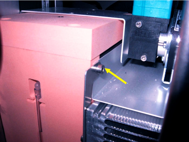
- Using a 3 mm hex key, loosen the two screws that secure the tops of the cooling fin brackets to the Cooling Module.
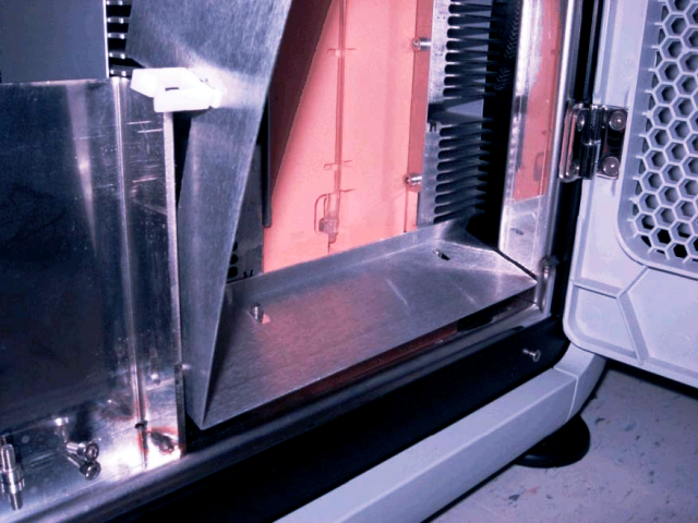
- Place the add-on shroud over the Cooling Module mounting studs located at the base of the Cooling Module.
Note — The rear flange of the shroud fits tightly under the cooling fins. It may be necessary to lift up slightly on the Cooling Module to install the shroud on the studs. This would require loosening the Cooling Module mounting nuts located under the Cooling Module fan. - Slide the slots in the upper tabs of the shroud onto the upper cooling fin bracket mounting screws on each side of the Cooling Module. Tighten the mounting screws.
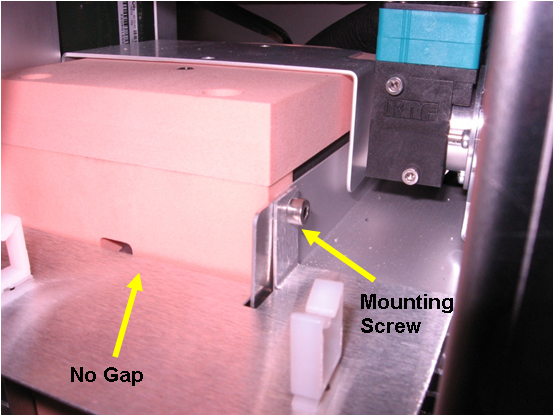
Note — The rear edge of the shroud should be flush against the front of the Cooling Module reservoir. - Secure the lower part of the shroud to the Cooling Module base with the two previously removed washers and nuts. Tighten the rear mounting nuts if loosened while installing the shroud.
- Secure the PCB bracket to the top of the Cooling Module with the two previously removed mounting screws.
- Route the Universal Fluids Drawer door switch cable through side clips.Note — Cable clips located on the top of the add-on shroud can be used for routing and securing cables.
- Close the system right-side door panel.
Verification
- Launch Service Software.
- Test the Universal Fluids Drawer door sensor open/close function.
 button at the top of the page to send feedback, comments, or change requests.
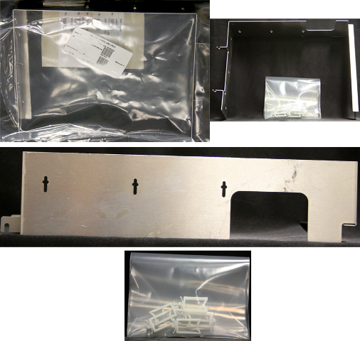