Chiller Ramp Upgrade Procedure
What is Affected
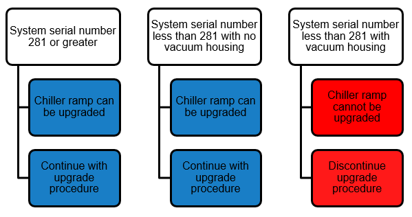
The New Chiller Ramp was cut in on production systems P0681 and above.
Installation of the New Chiller Ramp also requires installation of the Black Exhaust Shaft and Fan [903862].
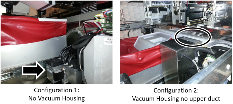
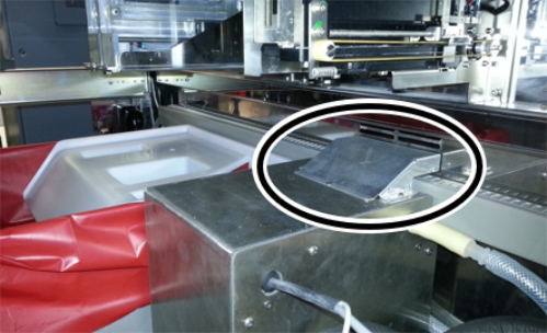
The Black Exhaust Shaft and Fan [903862] should NOT be installed on P281 and below.
The Black Exhaust Shaft and Fan [903862] has a shield in place to keep air from flowing up from the Chiller Heat Sink and toward the linear distributor.
Without that shield, the Chiller Ramp's Peltier heat is routed back into the Panther rather than the rear vent.
On systems in warm environments (Lab Temps ≥ 26 ˚C (warm but still in spec), Hot Peltiers, can report Chiller Seebeck voltage of range errors (High).

|
|
Parts and Materials Required
- 3mm Allen wrench
- CHILLER RAMP, MODULE
Time Required
- 1 Hour
Procedure
|
|
Warning—If replacing a NEW Chiller Ramp [903734], the Black Exhaust Shaft and Fan [903862] MUST be installed. If a Silver Exhaust Vent [903402] is installed, replace with a Black Exhaust Shaft and Fan [903862] |
- Put on proper PPE.
- Shutdown the Panther System and PC.
- Open the Universal Fluids Drawer.
- Open the right-side Panther system door.
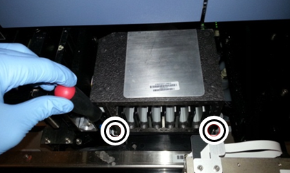
- Remove the existing Chiller Ramp.
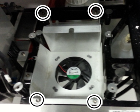
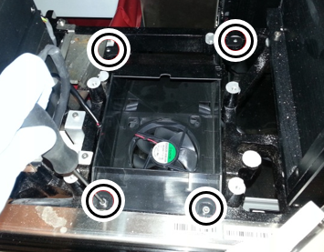
 Unscrew the four socket head cap screws holding the chiller ramp shroud in place with a 3mm Allen wrench.
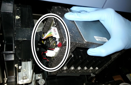
- Disconnect the cables on the underside of the shroud.
- Place the new shroud in the system.
- Attach the shroud to the Service Drawer with the 4 socket head cap screws using a 3mm Allen wrench.
- Place the New Panther Chiller Ramp in the shroud above the fan.
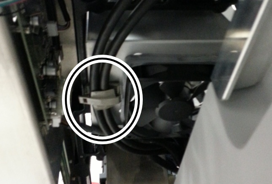
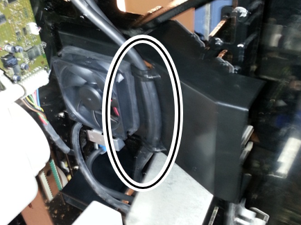
Note— Ensure the coalescing tubing on the back of the chiller fits into the circular opening in the shroud. - Route the cables removed from the old shroud bracket through the bracket in the new shrould.
- Connect the Chiller Ramp power and fan cables to the Chiller Ramp PCB.
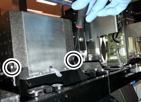
- Secure the Chiller Ramp with 4 socket head cap screws using a 3mm Allen wrench.
Note— You may need to reach around to the back of the Service Drawer through the side of the system to reach the rear screws. See image below. - Close the Service Drawer.
- Power on the System and PC.
Alignment/Calibration
- Update Panther instrument Firmware.
- Align the distributor to the New Chiller Ramp.
 button at the top of the page to send feedback, comments, or change requests.