Power Supply
The system has a +24V wide range main Power Supply. This main supply will accept input power in the range of 90 to 253 Volts and 50 or 60 Hz.
At the primary side, a power entry module with four included functions will be used:
- Appliance inlet
- Line filter
- Line switch
- Exchangeable fuse holder with a high breaking capacity fuse
At the secondary side, the +24V will be led to the COP PCB. The COP PCB contains the reset-able PTC fuses and the standard quick acting fuses. The fuses where required to protect against damage due to shorts. For the modules with a higher power consumption, like the incubators, two independent lines with each 5A quick acting fuses will be used for the limited circuits. The COP is able to provide as a maximum 2x120W to one module.
![]() The following diagram shows a principal overview of the power management.
The following diagram shows a principal overview of the power management.
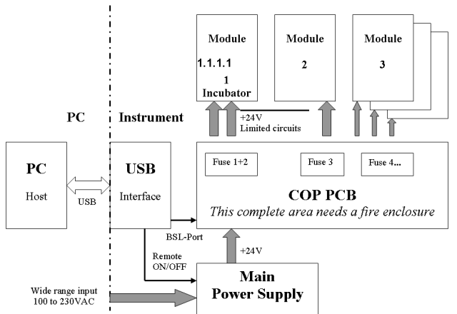
The COP is able to monitor the supply voltage after the fuses. Due to this fact, the COP detects over and under voltage conditions, for example a breaking fuse.
Power Supply on Module Level
A green power LED for +24V presence will be placed on the COP and every CU Module PCB to signal the FSE, that the module Power or the Power-CAN connection cable is properly plugged in. A DC/DC converter located on every module PCB will convert the +24V supply to +5V to supply the processor unit and the peripheral actuator and sensor logic.
Standby Mode
Entering the standby mode, COP will send standby commands to specific sub-modules to reduce the power consumption by reducing stepper motor hold currents or incubator temperatures. This parameter will be defined on the system stand by wake up time.
 button at the top of the page to send feedback, comments, or change requests.