Vacuum Pump Line Fuse Installation - 24V+ Power Supply
Parts and Materials Required
- Vacuum Fuse Board
- 3mm Hex Key
Time Required
- 30 Minutes
Procedure
- Put on proper PPE.
- Shut down the Panther System and PC.
- Disconnect the system and PC power cords.
- Open the left side panel door.
- Remove the door.
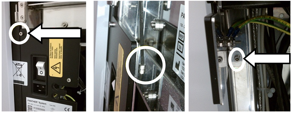
 Unscrew the 3 screws securing the Main Switch Bracket to the Panther frame.

Note—On some older Panther Systems the Main Switch Bracket may be welded to the system frame. - Gently remove the Main Switch Bracket and set aside being careful to not put stress on the cables attached.
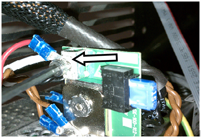
Note—There may be a label to the left of the Power Switch that will need to be cut in order to remove the Main Switch Bracket. - Unscrew the connector securing the Red vacuum power wire.
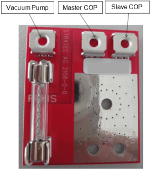
Note—This connector will also have two brown wires attached (+24V wires to COP). - Verify that there are no wires restricting access to the large round hole.
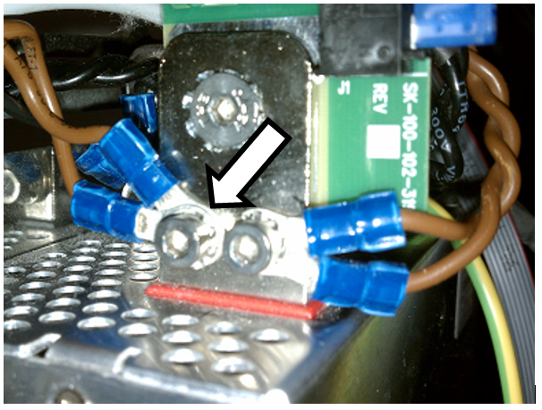
- Install the vacuum fuse board as shown below. Ensure the board is straight and does not obstruct the two tapped connector holes.
Note—Ensure that the attachment screw is tightened enough to deform the lockwasher teeth to prevent loosening. - Reconnect the COP's +24V brown wires to the connector.
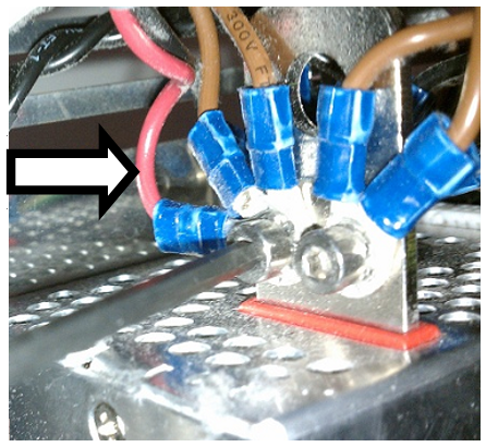
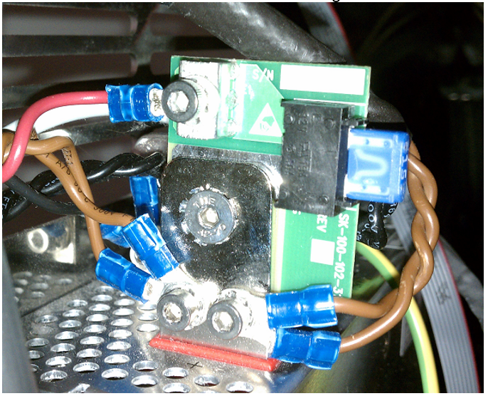
- Secure the Red vacuum power wire to the board as shown below.
- All wires should now be connected and look similar to the image below.
- Reinstall the Main Switch Bracket.
- Mount the left side door on the hinges and close the door.
- Reconnect the Panther System and PC power cords.
Addendum For New COP Wire Configuration
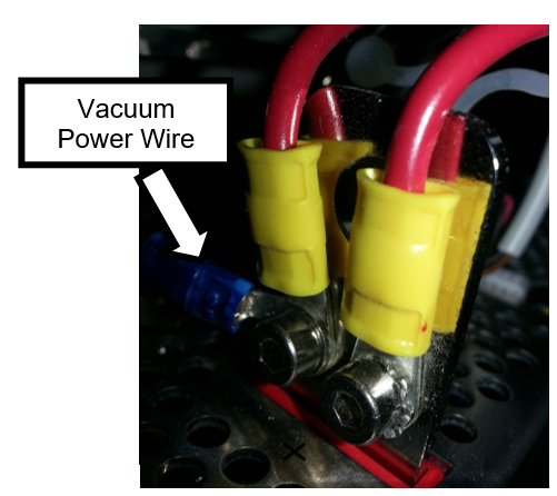
- Unscrew the 2 large gauge Red COP wires and Red vacuum power wire.
- Secure the vacuum fuse board as shown in the Step 5 below.
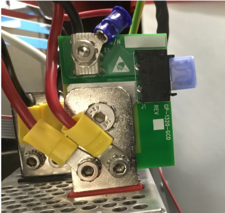
- Reconnect the 2 large gauge Red COP wires.
- Connect the Red vacuum power wire to the vacuum fuse board.
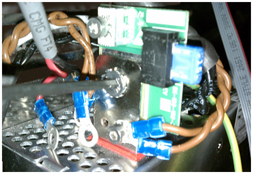
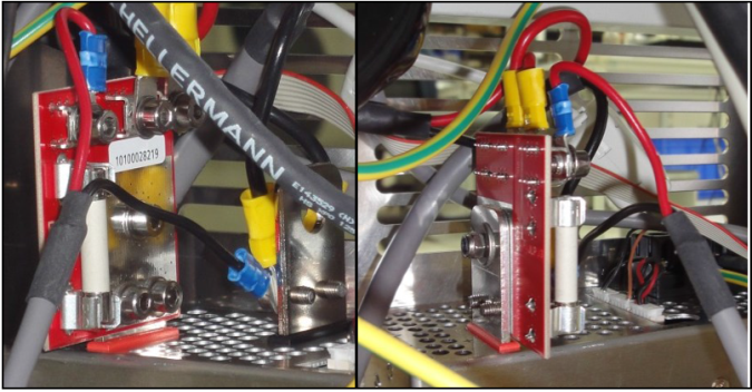
- All wires should now be connected and look similar to one of the two images below.
Verification
- Power on the Panther System and PC.
- Log in to the FSE shield.
- Open the Service Software.
- Initialize the Vacuum.
- Activate the Vacuum & Read the Vacuum pressure.
- Verify the vacuum is within specifications.
The vacuum level must read between -203mbar and -270mbar and the vacuum pump speed must read above 1650rpm.
If needed refer to Configuring the Quad Head Vacuum Pump Speed. - Exit Service Software.
- Start Panther Main.
- Check Vacuum in Panther Main.
- PrimeOperation of pumping fluid through tubing to ensure proper and consistent fluid delivery (remove air from the tubing, etc.). the system.
- Verify the Vacuum is within Specification:
- Maintains a vacuum level between 6inHg and 8inHg.
- Verify that exhaust is flowing through the rear vent (serial #00281 and higher) or through the routed tubing (serial #00280 and lower).
- Shutdown and restart the Panther System and PC in Customer Mode and return to customer.
 button at the top of the page to send feedback, comments, or change requests.
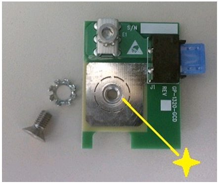