What is Affected
The vacuum pump is connected to the cooling module PCB. In rare cases of a short or an electrical issue with one or the other module, both modules could be affected. This upgrade will integrate an in-line fuse in the electrical line, bridging both modules to help isolate them in cases of electrical issues.
Parts and Materials Required
- Allen wrench, 3 mm
- FUSE BOX ASSEMBLY, VACUUM HOUSING
Time Required
- 15 minutes
Removal Procedure
- Put on proper PPE.
- Power down the Panther System and prepare it for service.
- Open the Universal Fluids Drawer to its fully extended position and open the right side panel.
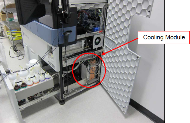
 Locate the Cooling Module.
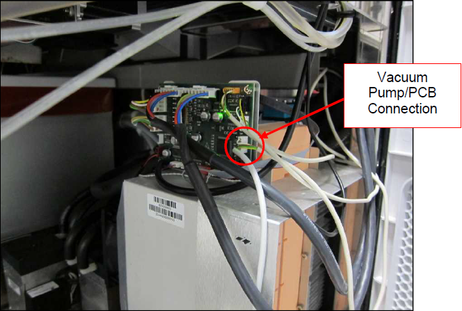
- On the Cooling Module PCB, locate the vacuum pump connector to the PCB.
- Unplug the vacuum pump wiring harness from the Cooling Module PCB.
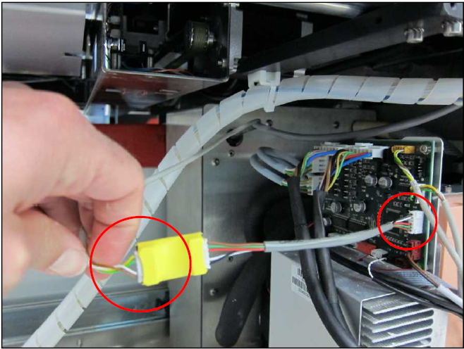
- Plug the new part (FUSE BOX ASSEMBLY, VACUUM HOUSING) into the now vacant vacuum pump connection on the PCB.
- Connect the vacuum pump wiring harness into the fused end of the fuse box assembly.

Note—Use a zip tie to secure any excess wire. Unsecured wires could potentially get stuck on moving parts of the system, such as the Universal Fluids Drawer. - Close the right side panel and the Universal Fluids Drawer.
- Power on the Panther System.
- Verify full system reset and that the vacuum level is within range.
 button at the top of the page to send feedback, comments, or change requests.
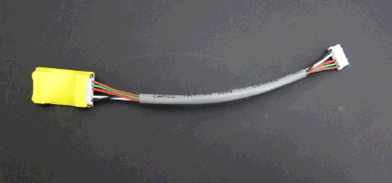